|
Detailed Review of Selected Non-Incineration and Incineration POPs Elimination Technologies for the CEE Region 6 Detailed review of selected POPs elimination technologies6.1 Selection of POPs elimination technologies for detailed review Available POPs elimination technologies have been reviewed in detail based on the background information described in previous chapters. Material and listed perceptions (e.g. a future divided CEE Region, environmental and economic "climate" supporting future establishment of POPs elimination initiatives) have been assessed for 4 commercially, in the sense of free market availability, POP elimination technologies. The review process has followed a number of steps, outlined in further details below, but in short it was selection of technologies and identification of appropriate and CEE Region selective evaluation criteria. Of utmost importance for the detailed review was that all reviews have been performed on technologies in operational mode, although GPCR was reviewed in a down-scale test plant facility. However, the facility was set in operational mode during the actual on-site review. 6.1 Selection of POPs elimination technologies for detailed reviewElimination of POPs differs from region to region. However, in the developing part of the world most elimination is based on various incineration techniques as an integrated part of the overall national approach to treatment of hazardous and/or municipal waste. These facilities furthermore are the basic of a systematic commercial system of treatment capacities for imported waste originating from countries in transition and/or without national treatment capacity. In e.g. Europe, the treatment capacities have increased, although the actual amount of treatable waste has reduced resulting in reduced treatment prices, tempting certain countries to export e.g. hazardous waste instead of initiating precautionary measures for waste reduction and transformation from hazardous to non-hazardous waste. In many parts of the world, and in particular in regions with economies in transition, like the CEE Region, former treatment habits are either non-competitive in economic sense with external commercial treatment facilities or non existing due to society transformation and economic decline. Considering the CEE Region as a group of countries in economic transition, the countries are facing a situation where national large scaled treatment facilities are almost unattainable due to mainly economic reasons, although recognising the enormous amount of hazardous substances potential for treatment. Alternatively, national priorities must outline which hazardous substances possess the largest risks to environment, human and biota enabling competent authorities to prepare certified actions through e.g. National Environmental Action Plans (NEAP). These could include investment into small-scale treatment capacities, allocation of funds for external treatment and/or various combined solutions allowing each country to gain experiences supporting a long-term sustainable solution. The key findings of Chapter 2 outlines the necessity of finding solutions for the CEE Region, which on one hand are realistic and originates in the region, but on the other hand have a long-term commitment to the international trend aiming at reducing any impact from chemicals to the environment, human and biota in general. As base for this review study, the requirements defined in chapter 4 must, to the extent possible, be compiled into any assessed solution. Selection of POPs elimination technologies for review is a difficult process involving a number of selective parameters as highlighted in earlier chapters. The review of previous performed POPs elimination reviews outline a number of alternatives to the existing elimination business mainly based on incineration technology. The project-frame leaves room for review of 4 technologies of which it has been decided that two should have their origin within the existing market platform primarily based on incineration methodologies, while the remaining two consist of alternatives hereto. The selection of present day available technologies in the CEE Region (e.g. cement kilns) and commercially economic viable technologies like semi-mobile incinerators and non-incineration alternatives hereto, will allow key deciding resources within the national CEE administrations to have a better overview of advantages and/or disadvantages of a given technology. The review and comparison data will in first place be compiled objectively without any interpretation of results in relation to national, regional and/or international requirements. This allows the technical experts to concentrate on performing a consistent review as basic for the later discussion. The reviewed basic data have been presented to the advisory group members of the project involving both main NGO forums and the consultant management experts. A more detailed review of alternatives to incineration based technology reveal a situation where certain non-incineration alternatives are more commercial developed than others. Among the most recent outlined list of “fully” commercialised alternative non-incineration technologies (reference to UNIDO paper “Available non-combustion POPs destruction technologies, October 2001”) are:
Additional, a number of 3-4 other alternatives are classified as “emerging technologies” and finally a few additional are classified as “demonstration technologies”. Finally, a number of CEE based alternative merging technologies are screened including e.g. the Russian developed Cyclone technology. Of the Russian facilities investigated so far, the cyclone plant appears to be technically and environmentally the most promising. They have minimised the problem with solid waste and made recycling of the sodium chloride possible, and they have operating experience on dioxin treatment. Furthermore, they seem to have documented satisfactory results treating constituents similar to PCB. This will be further evaluated in the ongoing NEFCO Fast Track project. As basis for the final selection of two non-incineration technologies subject for review, the project has decided only to review technologies, which are characterised as “fully commercial available”. Commercial available technologies mean that the technology has already been successfully operated in a full scale commercial (or other institutional) setting, and that vendor or vendors are available who can provide not only the technology itself, but also can provide the know-how and support needed to successfully set up and operate the technology under circumstances such as those likely to be encountered in the CEE Region. Furthermore, the project has per default decided only to focuses on “inert” technologies, which are dedicated for the purpose of performing destruction of POPs chemicals. Only deviation is the including of cement plants, which originally are set up as cement production units and where chemical destruction is a side activity utilising the high temperature production methodology. The selective process of only involving dedicated POPs destruction technologies, beside cement kilns, furthermore supports the fact that many countries are looking for economic viable solutions, which partly could be based on a co-financing model involving bilateral as well as regional funding mechanism. The project focuses on accessibility to primary affordable technologies supporting the philosophy of countries gaining their own experiences when initiating the necessary planning process, implement public participation, secure necessary and skilled staff allocation, prepare and carry out educational programming and secure sufficient infrastructure supplies. The anticipated and partly confirmed magnitude of the problem (amount of obsolete pesticides and POPs) necessitates immediate actions related to the final elimination of these substances. Selection of possible applicable elimination technologies must reflect both the critical conditions and possible impact from these partly uncontrolled stockpiles, but also be instrumented in an accessible form allowing countries to proceed with elimination of hazardous substances on the one hand and instrument precautionary measures towards waste reduction with the other. After consultation with the Advisory Group, the below two non-incineration technologies were selected for further review. The technologies were found as the optimum technologies complying with the CEE Region's objectives for POPs elimination:
The final choice complies with recommendations put forward in the DANCEE report “Review on Obsolete Pesticides in Eastern and Central Europe”, May 2001, recommending the same non-incineration technologies for further review in terms of their applicability for the CEE Region e.g. as BAT for POPs elimination. Therefore the following non-incineration technologies have been chosen for detailed review in this project:
In addition to the two selected non-incineration technologies, two incineration technologies have been selected. Pre-conditional for this selection, the consultant has put forward a number of statements, which have been used during the selection procedure. These are:
Analysing the above characteristics of the region, the selection process must also consider the variety of national policies regarding hazardous waste management and willingness to comply with international environmental instrumentation (protocols and conventions) in general, defining potential applicable POPs elimination technologies suitable for the CEE Region. The DANCEE report “Review on Obsolete Pesticides in Eastern and Central Europe”, May 2001 recommended that the following incineration technologies to be subject for further review in terms of their potential for the CEE Region, as e.g. BAT for POPs elimination:
The selected non-incineration technologies follows in line with the result of recent preliminary assessment review of more than approx. 15 different available non-incineration technologies, performed within the frame of the ongoing UNIDO POPs project. The selected incineration based technologies cover technologies, which at present, are seen as the most widespread in the CEE Region (cement kilns) and most trustworthy incineration based alternative (dedicated incinerators) to the established “elimination infrastructure” within the region. The detailed review of the 4 selected technologies was performed by a team of engineering and environmental experts from COWI A/S. The team managed to oversee all four selected technologies in on-site operational mode, although GPCR and semi-mobile incineration facilities were in testing mode, due to lack of on-time fully operational full-scale units. In Table 6.1 time and contact persons from each of the visited technologies are outlined. Table 6.1.1 Contact persons and vendor information
6.1.1 Mobile versus stationary plantsIt is often discussed if a plant shall be mobile or stationary as optimum POPs waste elimination technology. Stationary plants has several advantages in favour of mobile units, like
Nevertheless, mobile units are normally more economic accessible due to lower capital costs, they normally have lower capacity enabling countries to work with low-capacity units as a playground for gaining experiences and finally mobile units could be regarded as more accepted by the public due to their “temporary outfit”. We have examined the mobility of all the plants in this report, but we believe that even though a plant is declared mobile, it will have a tendency to become stationary. 6.2 Review criteriaWithin the last 5-year period, a number of detailed POP elimination technology studies have been carried out primarily driven by US demand for destruction of stockpiled chemical weapons. In continuation of the negotiation process leading forward to the Stockholm Convention, a number of dedicated studies focussing solely on POPs destruction opportunities and preparatory guidelines have been initiated both through the UN-system as well as on bilateral basis. One of the key documents are the ongoing preparatory process under the Basel Secretariat (Technical Working Group) leading to a guideline on the environmentally sound management of POPs as waste herein included demand for present and prospective future elimination of POP compounds. The technical guideline is expected to be present during COP session under the Basel Convention during October 2004. Furthermore, Article 6 in the Stockholm Convention outlines: “Disposed of in such a way that the persistent organic pollutant content is destroyed or irreversibly transformed so that they do not exhibit the characteristics of persistent organic pollutants or otherwise disposed of in an environmentally sound manner when destruction or irreversible transformation does not represent the environmentally preferable option or the persistent organic pollutant content is low, taking into account international rules, standards, and guidelines, including those that may be developed pursuant to paragraph 2, and relevant global and regional regimes governing the management of hazardous wastes;” It is clear that the intent of the treaty is to "destroy" POP compounds in an economical favourable way and also at the same time avoid the formation and release of POPs. As such, those technologies which can most effectively deal with the POPs wastes, and minimise or eliminate any further production of POPs wastes or formation or release should be rated highest. In the overall assessment of the technologies, a rating system has been used where 5 is "Bad", 4 "Below average", 3 "Average", 2 "Above average" and 1 "Best". 6.2.1 EnvironmentGiven a certain amount of substance to be treated, elimination technologies may differ from each other environmentally with respect to:
The environmental impacts related to the differences may include global warming, depletion of the stratospheric ozone layer, acidification, eutrofication, photochemical ozone creation, ecotoxicity, human toxicity, different types of filling requirements, land use (may include area requirements as well as biodiversity etc. – not yet generally accepted as impact category) and consumption of natural resources and materials (assessed for each resource/material). The assessment tools are generally characterised as Life Cycle Assessment (LCA) tools, which typically is divided in tools for detailed calculations and tools for screening/hot spot assessments. The choice of tool to be used normally depends on:
In screening assessments, only the most important impact categories are included. Besides that, indicators may be used to simplify some categories. E.g. energy consumption may be used to represent global warming, acidification and to some extent also categories like eutrofication, photochemical ozone creation and toxicity, which partly are influenced by energy production. Considering that some of the elimination technologies are only available for review at pilot scale level, reliable data may not be available to an extent justifying a full detailed LCA, besides that a full and detailed LCA may require more than one man month of work for each technology, it is proposed to adopt a screening/hot spot assessment. This screening/hot spot assessment has focused on the following characteristics (a reference of 1 kg of POP substance treated is used in all cases):
6.2.2 TechnicalIn order to make a detailed technical evaluation of selected POP elimination technologies, a number of different, and to large extent non-comparable criteria, must be assessed. These are as a minimum:
6.2.3 EconomyFrom an economic point of view, a given POP elimination technology option is not merely a matter of chemical processes and equipment. The long-term objective of the project is to make an impact in the recipient countries in terms of actually eliminating POPs. To achieve this, a number of barriers and pitfalls will have to be closely observed, not only in terms of each technology's technical and environmental performance, but also in terms of the institutional, organisational and financial constraints posed by each individual technology. From the economist's point of view, the problem can therefore be formulated as follows:
The project covers a wide array of countries and regions, which all have their specific characteristics relevant for dealing with the POPs problem. These characteristics include:
The extent, to which the long-term objective can be met, very much depends on the actual circumstances in each country, or even in each region within the country. The present project does not consider location specific solutions, which means that the criteria put forward must be generic to a certain extent. Economic criteria Organisation Transfer of know-how Capacity Robustness Logistics Process residues Demand Analytical costs 6.3 Destruction technologiesIn the last 30 years increasing problems with hazardous waste have been recognised in most countries worldwide. Hazardous waste is the most toxic part of the general waste problem. Often even small amounts of hazardous waste can be more harmful than big amounts of normal organic household waste. As all POPs are hazardous waste, they are also covered in this description. Hazardous waste stems normally from industry, producing all kinds of normal very useful products. Everybody is today surrounded by products, which in the production phase have resulted in hazardous waste. From the cloth, spectacles, jewellery we use to the floor, wall, ceiling, kitchen elements, water tap, zinc, light bulbs, lamps, windows, pots and pans etc. in our homes. From the bicycles, cars, busses, trains, aeroplanes to the roads, rails for our transport, to our working places. Everywhere you turn there are valuable products, which in the production phase is likely to produce hazardous waste. This project review has tried to focus on the scenarios of available POP elimination technologies possessing the least secondary problems. POP waste must be treated to the highest degree possible according to the requirements and intents of the Stockholm Convention. In the following Section, please find a detailed environmental, technical and economical review of the 4 selected POP elimination technologies. Furthermore, in Section 6.8, a brief description and assessment is made for one of the most promising technologies developed within the CEE Region (Russia), the Cyclone Reactor. 6.4 Gas phase chemical reduction (GPCR)6.4.1 IntroductionGas phase chemical reduction (GPCR) developed in Canada by Eco-Logic has been heralded as an alternative to incineration. The process involves the gas-phase chemical reduction of organic compounds using hydrogen at temperatures of approx. 850°C and ambient pressure. The organic compounds are reduced by hydrogen to give methane, other light hydrocarbons, and hydrochloric acid gas (chlorinated waste streams). The hydrochloric acid is neutralised by addition of caustic soda during initial cooling of the process gas. Dioxins and furans are not formed due to the reducing conditions prevalent in the reactor. The process needs tight control to ensure the hydrogen gas and flammable product gases do not form explosive mixtures with air. Destruction efficiencies are high and the system can theoretically operate without an external source of hydrogen, although this does not occur in practise due to the increase in complexity. The process is non-discriminatory, decomposing all organic compounds. With the addition of thermal desorption front-end systems, the process can treat contaminated soil and electrical equipment, and can also evaporate volatile pesticides directly from drums. Many demonstration tests have been performed using the GPCR process and Eco-Logic has designed, built and delivered portable demonstration plants to both American and Japanese clients. Eco-Logic has operated two full-scale plants, one in North America and one in Australia. From 1995 to 2000, Eco-Logic treated in the excess of 2,000 tonnes of waste at the full-scale plant in Australia with 1,500 tonnes being treated in the last two and a half years of operation alone. During those last two years, Eco-Logic installed a bigger, new Thermal Reduction Batch Processor (TRBP) for the solid waste treatment that had greater capacity, greater reliability, and decreased cycle time. The plant could then operate with two TRBPs and concurrently treat liquid PCB waste resulting in improved process performance. 6.4.2 Description of the technologyThe GPCR process is a closed process. The treated solids are analysed before release, the treated flue gas is collected in tanks and analysed before release (by gas chromatographic techniques). The treated scrubber water is collected and analysed before release. The process is based on gas-phase reaction of hydrogen with organic compounds. At 850°C or higher, hydrogen combines with organic compounds in a reaction known as reduction to form smaller, lighter hydrocarbons, primarily methane. For chlorinated organic compounds, such as PCBs, the reduction products include methane and hydrogen chloride. This reaction is enhanced by the presence of water, which acts as a reducing agent and a hydrogen source. The process is non-discriminatory; that is organic compounds such as PCBs, PAHs, Chlorophenols, Dioxins, Chlorobenzenes, pesticides, herbicides and insecticides, chemical warfare agents are quantitatively converted to methane. The overall outline of the reaction mechanism is shown in Figure 6.4.1. below:
Figure 6.4.1 GPCR reaction scheme. Hydrogenation Hydrogen has been used in large quantities in the petroleum refining, chemical, petrochemical and synthetic fuel industries for decades. Therefore, the use of hydrogen in industry is fairly routine. The electrical utility industry has also successfully used hydrogen gas for more than forty years, for such operations as cooling rotor and stator coils in large turbine generators. Hydrogen is an accepted fuel in the aerospace industry, and has been safely handed for years in large quantities. Although hydrogen has been used in industrial processes for decades, it is relative unknown to the public. However, there are strict guidelines for the safe handling and use of hydrogen from the authorities. Disadvantage Advantage Furthermore, the hydrogenation process has a very low side production of dioxins and other harmful compounds in comparison to e.g. the incineration process. 6.4.3 Description of the plantThe GPCR process is comprised of a central reactor for the actual destruction of organic waste, with an attached multi-stage scrubbing system to remove inorganic contaminants and light hydrocarbons from the reacted gas stream. Depending on the waste type, various waste preparation and feed mechanisms are used to introduce the contaminants to the reactor. All of the equipment comprising the GPCR process is broken down into Major Equipment Groups (MEG). Each MEG has an associated equipment list with specifications and a Piping and Instrumentation Diagram (P&ID). The MEGs and their descriptions are presented in Table 6.4.1. Table 6.4.1 Summary of the GPCR process control MEGs
In Figure 6.4.2 please find a process diagram showing the overall process components and their treatment potential (liquids, soil, sediments, bulk etc.) and the process material streams. Click here to see Figure 6.4.2 Figure 6.4.2 Process diagram Click here to see Figure 6.4.3 Figure 6.4.3 The process diagram divided into MEG's 6.4.4 Description of the operationA detailed description of waste preparation and feeding actions needed is outlined in the following. Bulk solid material When treating transformers, the PCB oil is drained before the transformer is loaded into the TRBP. The organic contaminants in the waste are thermally desorbed and swept into the reactor by the hydrogen-rich, hot recirculation gas. During full-scale operations in Australia, the TRBP treated 15 tonnes of waste in open drums. The drums are then sparged with hot hydrogen. Wipe tests following GPCR verified the drums to be free of organic contamination allowing the drums to be disposed of off-site. Contaminated electrical equipment processed in the TRBP constitutes a relatively small organic load to the GPCR reactor. High-strength organic wastes such as Askarel can be processed simultaneously. The TRBP is also suitable for processing high-strength organic wastes such as obsolete pesticides, which are sufficiently volatile to evaporate directly from drums. One advantage of this approach is reduced waste handling, which minimises fugitive emissions at the site. Watery wastes and high-strength oily wastes Soil and sediments Waste treatment Some of the gas is reheated and re-circulated back into the pre-heater or through the TRBP as sweep gas. Excess product gas is removed from the system, compressed and stored. The stored product gas is continually analysed and subsequently used as fuel to heat the TRBP, pre-heater, or burned in an auxiliary (excess) gas burner. Output recovery Water Treated bulk solids
The product gases are continuously monitored using a micro-gas chromatograph to detect possible organic pollutants. Before the product gas is sent to the product gas burner, it is analysed to ensure it is free of organic contaminants. This allows for continuous monitoring of product gas (both immediately after processing and in the compressed storage) for specific compounds indicative of incomplete destruction of waste. Product gas outside normal operating maximums is re-routed to the pre-heater for re-processing. Data are stored historically in the process control computer for future analysis and review. Limitation to the process 6.4.5 Plant capacityThe throughput capacity of the GPCR process is dictated by the number of TRBP units installed. However, it seem as all capacities have a cost interval close to 1,000 USD/ton of pure chemical treated (e.g. PCB/chlorbenzene mixture with 50% chlorine). If the hazardous chemical fraction of the waste is less, the treatment price per ton will be lower (e.g. if a pesticide is formulated with a lot of talcum (e.g. up to 99%) then the treatment of the active substance will be quicker). On the head-office location in Toronto, Eco-Logic has in Canada a demonstration facility with a capacity of 5-50 tonnes/year. Furthermore, capacity is established in Japan with a mobile facility of 850 tons/year. Formerly, Eco-Logic operated a full scale facility at 1,800 tons/year in Australia and St. Catharines in Canada. For the purpose of making possible up-scaling of the technology in order to increase its availability to the CEE market platform with extensive amounts of POP/OP waste, the following additional must be compiled:
6.4.6 Practical experienceEco-Logic has considerable practical experience with the GPCR system. The GPCR process was demonstrated in public for the first time in 1991 treating harbour sediment containing coal tar at concentrations up to 300 g/kg. The concentration of PCBs in the air emissions, liquid effluent and processed solids following GPCR treatment were all below the detection limits resulting in a documented PCB Destruction and Removal Efficiency (DRE) of at least 99.9999%. Over the past 10 years, Eco-Logic has successfully completed a variety of demonstration projects, including the US-EPA SITE demonstration in 1992 and numerous testing programs for the US Army under their chemical demilitarisation program. The majority of waste treatment activities using GPCR have occurred at Eco-Logic's full-scale commercial plant in Kwinana, Western Australia, which began commissioning operations in 1995 and achieved commercial throughputs by 1998. The plant operated through 2000, and treated in excess of 2,000 tonnes of waste including PCBs, pesticides and other POPs, with most – up to 1,500 tonnes –treated in the final 2.5 years. Another large-scale operation was conducted at General Motors of Canada Limited (GMCL) in St. Catharines, Ontario. This demonstration project, which began in February 1996 and concluded in September 1997, destructed approx. 1,000 tonnes of PCB-contaminated electrical equipment (transformers, capacitors, ballasts), concrete, oil, soil and miscellaneous other solids and liquids. Recently (2000), the plant participated in the US Assembled Chemical Weapons Assessment (ACWA) program under contract to the US Army, with success. This testing included a thorough risk analysis which addressed important design changes in the full-scale plant designed for the Army. To date, more than 3,000 tonnes of contaminated waste, including PCBs, dioxin, HCB and chemical warfare agents, have been treated using the GPCR technology, and more than 30,000 commercial operating hours have been recorded. Demonstration plants continue to operate in North America and Japan. 6.4.7 Maintenance and services requirementsThe GPCR process, as mentioned previously, is a closed loop process. Nearly all the processing has been made automatically regulated via an SRM (Steering, Regulating and Monitoring) computer. Most of the streams are fitted with actuator valves, pressure meters, thermometers, and at selected places there are hydrogen measurements. One of the biggest challenges is to keep the system airtight. For that reason special packing and seals are used. These packing and seals are of Teflon, Viton and synthetic rubber - EPDM (Ethylene Propylene Diene Monomer), which are available off-the-shelf. The GPCR reactor is Hastelloy stainless steel, which is available all over the world. The problem of the availability of packing, seals and actuators may be solved by having the necessary stocks of maintenance material. Hydrogen, nitrogen, and activated carbon are easily attainable, which means maintenance issues may be easily overcome. The following supply lines and raw materials are required for plant operations. Supply lines
Raw materials
6.4.8 Occupational health and safetyThe most important occupational health problems occur in connection with the handling and loading of the waste before treatment. This concern is mitigated by handling waste in drums, and if necessary to work with appropriate personal protective equipment (PPE). Any hydrogen that may leak into the working area is detected by hydrogen detectors placed in central places. The working area is ventilated and all electricity is ex-proved to secure against electricity induced ignition. Therefore, explosion risk due to hydrogen seems to be eliminated. Noise may be a problem when the compressor for the product gas is running. Because of the continuously heating of both the TRBP and the reaction chamber, devices must be well insulated to prevent the working area from getting too hot. 6.4.9 Operational risksIn 1998, Richard W. Prugh from Process Safety Engineering, Inc. conducted an independent review of the safety of the GPCR technology, specifically to examine the use and handling of hydrogen in the process. He identified potential hazards associated with the use of hydrogen in the GPCR process at that time and made 19 recommendations to improve the plant. Since then, design changes to the GPCR process have been implemented based on Mr. Prugh's process design recommendations, although his design recommendations were primarily related to the use of GPCR as part of a Total Solution for chemical weapons treatment. In 2001, as part of the work conducted for the US Army for the Assembled Chemical Weapons Assessment (ACWA) program, the GPCR technology underwent a preliminary hazards analysis, which is reported in the following publication "Engineering Design Package Volume VII, Preliminary Hazards Analysis, 14 December 2001" prepared for the Assembled Chemical Weapons Assessment Program, US Army. From the independent review and the preliminary hazards analysis, it may be concluded that Eco-Logic's GPCR technology operates to strict risk reduction criteria and is intrinsically safe. 6.4.10 Plant mobilisation/demobilisationFor a 3,000 tonnes/year plant it takes 2-3 months to dismantle - move and re-erect the system somewhere else. The cost of re-locating a plant facility is in the range of 15-25% of the initial capital costs with additional costs required for sampling, analysis, and transportation. It is estimated that the 3,000 tonnes plant facility could be moved for a maximum of 3 to 4 Mill USD incl. decommissioning, transport, crane assistance, re-installation and re-commissioning. 6.4.11 Capacity buildingEco-Logic has twice proved that they can transfer the know-how of running the plant to a new company. An objective of the ACWA demonstration testing program for the US Army was to demonstrate that government operators could be trained to operate the GPCR technology. This objective was successfully completed since Tennessee Valley Authority personnel operated the GPCR process after receiving training from Eco-Logic on technology operation. Also Eco-Logic's Japanese partners were trained with success. The training is made easier because there are only a few critical process parameters that have to be followed (such as temperature, hydrogen concentration, and the amount of water vapour, etc.). 6.4.12 Environmental impact of the technologyThe assessment of the environmental impacts is based on the criteria presented in Section 6.2. Materials consumption The annual amount of waste treated in a "normal one reactor facility" is assumed to be in the range of 1,000-1,800 tonnes although depending on the waste type. Assuming an overall life of around 10 years of the plant constructions, the consumption of construction materials will be in the range of 0.06-0.11 kg pr. kg of waste treated. Assuming an overall recycling rate of approx. 90%, which should be considered realistic in most countries, the consumption of construction materials is reduced to ≤ 0.01 kg material pr. kg of waste treated. Compared to the consumption of means of operation indicated below the consumption of construction materials should be regarded as insignificant. It should, however, be noted that no information regarding material composition of special alloys/equipment has been available. Thus, it is not known whether these alloys and equipment contain very scarce and valuable materials. The main means of operation and consumption related to the selected waste types are listed in Table 6.4.2. Among the minor ancillary materials consumed but not listed in Table 6.4.2 may be mentioned activated carbon used for cleaning of air and water emissions. The mass of carbon used corresponds to around 6-7% of the waste treated (measured as dry matter on a mass basis). The carbon is after use treated and destructed in the plant parallel to other waste. Table 6.4.2 Consumption of important means of operation
*1: Waste types are characterised as follows: Of the means of operation listed in Table 6.4.2, electricity is a energy source and will be considered only as such while natural gas is a non-renewable resource used as energy source, and therefore will be considered in terms of material consumption as well as energy consumption. Finally, sodium hydroxide should be regarded as a renewable resource as well as a source of energy consumption as energy is being used for extraction, preparation and refining. The material consumption for the GPCR-process related to the selected waste types may thus be presented as in Table 6.4.3. Table 6.4.3 Material consumption related to the GPCR process
*1: Waste types are characterised as follows: Energy consumption Table 6.4.4 Energy consumption related to the GPCR-process
*1: The energy consumption related to consumption of natural gas is based on a figure of 48 MJ/kg gas, of which 45 MJ is the energy content and 3 MJ is the energy used for extraction and refining of gas. Chemicals, emissions, residues and elimination efficiency Table 6.4.5 Generation of emissions and residues
*1: Waste types are characterised as follows: The available data on the content of POPs and similar substances including decomposition substances in emissions and residuals from the GPCR-process have been summarised in Table 6.4.6. It is noted that measurements addressing the substances treated or organic chlorine in general have been available only with respect to PCBs and only with respect to air emissions. Thus, it is only possible to partly assess the elimination efficiency of the GPCR-technology. Table 6.4.6 Content of substances in emissions and residues by treatment of PCBs by the GPCR process
NDA: No data available. Using the amount of organic chlorine and the amount of relevant substances as measurement units, DRE (destruction and removal efficiency) can be estimated as shown in Table 6.4.7. However, due to lack of data it is not possible to assess DE (destruction efficiency). The concepts of DE and DRE are defined and discussed in Section 6.6.2. Table 6.4.7 Assessment of DE and DRE for the GPCR-process
*1: Waste types are characterised as follows: Other issues 6.4.13 EconomyBased on information from Eco-Logic, the following general pricing can be outlined for the establishment of annually POP elimination treatment capacity of 3,000 and 10,000 tonnes, respectively. Annual treatment capacity - 3,000 tonnes
Annual treatment capacity - 10,000 tonnes
The cost estimates largely includes license, design, hydrogen production and overhead. Labour costs are of course country dependent. By experience from increasing international demands for technology control and assessment, analytical costs can comprise up to 50% of the project costs for demonstration facilities. 6.4.14 Evaluation of the GPCR technologyTechnical evaluation GPCR has historical, full-scale commercial experience. There are still believed to exist some technical risks associated with scale-up of batch processing with assembled chemical weapon feed streams and generation of carbonaceous material in GPCR, although the vendor claims that these has been overcome within e.g. the ACWA program. The primary destruction process for the chemical agent operates at low temperature and ambient pressure. The GPCR process utilizes four major hazardous process chemicals: sodium hydroxide, hydrogen, kerosene and natural gas. Some of these materials are used in large quantities, and all pose some routine exposure risk to workers during feed preparation and maintenance of process equipment. However, all process materials for the GPCR process have moderate to low toxicity and persistency, are commonly used in industry, and can be handled in accordance with well-established industrial safety practices. Analysis Wood spiked with PCP was treated in the GPCR with no detectable PCP (at levels as low as 1,300 µg/m³) in the product gas. GPCR has previously been permitted under "Toxic Substance Control Act" for PCB destruction, with tests showing >99.9999% DE.
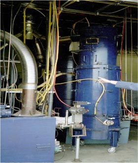
Figure 6.4.4 The Thermal Reduction Batch Processor, Canada June 2002 Scrubber Maturity Individual feeds require individual control strategies for heat input to the TRBP, and additional data for each feed is required to develop these strategies. In addition, the passage of excess energetic (e.g., un-dissolved burster material) to the TRBP is still of some risk because the operational safety margins for expected feeds are not known. There are known or standard preventive and routine maintenance requirements for the commercial GPCR. Requirements for cleaning carbonaceous residues and other solids out of TRBPs, GPCR reactors, and downstream gas polishing units could be extensive. Eco-Logic states that the above comments are irrelevant to conventional hazardous waste – they have proven that the problems identified can be easily Monitoring During an automatic shutdown of GPCR, the shutdown procedures for GPCR were implemented properly, indicating that the control system had performed adequately. The computer control system and its programmed alarms and interlocks were adequate to allow for safe and controlled shutdowns each time they occurred as intended. However, control of the heat input to the TRBP (the primary control of GPCR) is manual, putting a large responsibility on the operator. There is a potential in GPCR for the slow, controlled rate of heating to exceed the level at which gas evolution is effectively controlled. Pressure spikes in the TRBP occurred during several validation runs, but they were handled by the control system.
Figure 6.4.5 A 1m³-version of the TRBP, Canada, June 2002 Nonetheless, the amount of gas evolution may be of concern at full-scale. In demonstration and at full-scale, high gas evolution is controlled by operating two compressors at all times with a third used as a backup. As a minimum, the nature of GPCR requires “trial and error” treatment methods with multiple runs of every type of feed proposed for full-scale. This is required in order to gain experience with how fast the heat transfer to the TRBP can be ramped up. Completeness of effluent characterization Two concerns exist relating to the GPCR system, chemical agent monitoring in the GPCR product gas stream and control of energetic levels in the feed, which can be resolved through improved design and additional development. GPCR utilize process materials that are commonly used in industry, and can be handled in accordance with well-established industrial safety practices. GPCR is a remote operation, which generally protect workers from chemical and physical hazards. However, there are still inherent risks associated with a high volume of hazardous chemicals used in the process, and the use of high temperature hydrogen in the GPCR process. GPCR operates at high temperatures (above 815°C), and utilizes hydrogen (a potentially explosive or flammable gas) in the process. However, the safeguards, monitoring, and controls that minimize worker impact in the event of a facility accident are similarly beneficial with respect to public impact. These provisions mitigate the risk of an accidental release of agent or process chemicals that could otherwise disperse to the public. Even if an accident occurred during operations, public impact is minimized or eliminated since several layers of system and facility secondary containment should sufficiently contain the effects and prevent public exposure. All waste streams generated during demonstration were characterized with the exception of GPCR gas effluents during agent operations. Proposed full-scale disposal options were specified for all waste streams. There are no external liquid effluents. The only solid products from the total solution include solid residue from GPCR. Solid residue from GPCR collected during the demonstration passed the TCLP (toxicity characteristic leaching procedure) requirements. The gaseous emissions from GPCR will undergo "hold, test and release" prior to use as a fuel. All primary destruction processes and their associated intermediate waste streams are held tested and reworked (if necessary) before release. GPCR product gas (containing hydrogen, methane, CO2, CO and acid gases) is scrubbed with caustic and then held for agent testing. Once cleared, the product gas is burned in a boiler or other energy recovery device and the combustion products are then passed through a catalytic converter.
Figure 6.4.6 The GPCR reactor in Canada, June 2002 The gas product from GPCR is in principle a hazardous waste, but may be burned in the process if it meets certain requirements (the boiler or industrial furnace (BIF) exemption). Based on demonstration results, it appears that the GPCR product gas exceeds the minimum required heating value of 5,000 BTU/lb, which is used as a key test to determine the applicability of the BIF exemption. In summary, there are no liquid effluents, and the gaseous and solid effluents from demonstration appear to present a low hazard. GPCR gaseous effluents are held, tested, and reworked (if necessary) prior to release. However, the overall impact on human health and the environment could not be fully ascertained due to the lack of validation for the method for detection of agent in GPCR gas effluents. GPCR has a history of successful permitting for PCB destruction in the US. The permitting strategy includes discussion of options for effluents to air (GPCR gases to boiler, and other air effluents through plant filters (burning and/or active carbon filter) with no expected permitting issues), no discharges to water are proposed, and all solid wastes are treated and decontaminated completely of agent and may be released for general use or sold to the public. Environmental evaluation Material consumption Table 6.4.8 Comparative assessment of material consumption
-: Insignificant Energy consumption Table 6.4.9 Comparative assessment of energy consumption
Chemicals, emissions and elimination efficiency Considering, furthermore, the very low level of dioxin emission to all media and residues from the GPCR-process it seems appropriate to rate this process as good and clearly above middle as outlined in Table 6.4.10 below. Table 6.4.10 Assessment of emissions and elimination efficiency
?: No data available Other issues Table 6.4.11 Residues
-: Insignificant 6.5 Base catalysed dechlorination (BCD)6.5.1 IntroductionIn April 2002, the review expert team visited the ongoing Base Catalysed Dechlorination (BCD) process plant used on the Olympic Coordination Authority site at Homebush Bay, New South Wales, Australia for degradation and final elimination of organic chlorine compounds. The original plant design was based on a pipe flow reactor concept. Problems encountered during the commissioning phase and subsequent plant modifications resulted in the conversion of this pipe flow reactor into a batch plant utilising an agitated, externally heated reaction vessel, with caustic shearing and oil pre-heating systems. This description specifically covers the BCD plant in its current agitated vessel configuration. The Sydney Olympic Site During the general remediation earthworks on the Olympic site, any materials suspected to be contaminated with SCW and/or dioxin/furan, were segregated out for separate treatment. This segregation resulted in approx. 450 tonnes of soil contaminated with SCW and dioxin/furans. In addition about 10 tonnes of pure SCW concentrate required treatment. Under the NSW Environmentally Hazardous Chemicals Act (1985), an SCW is defined as any chemical listed under Schedule 1 of the regulations appended to the act. These compounds are mainly persistent chlorinated organic pesticides including Chlorobenzenes (CBs) and Chlorophenols (CPs). In the case of the Sydney Olympic project, the SCW compounds of concern were determined to be as follows:
Other compounds of concern that required treatment included 2,4,5-trichlorophenol, 2,4,6-trichlorophenol, 1,2-dichlorobenzene, 1,4-dichlorobenzene, 1,2,3,4-tetrachlorobenzene and 2,3,4,5-tetrachlorophenol. Enterra used an Indirect Thermal Desorption (ITD) plant to remove the contaminants from the soil, generating approx. 13 tonnes of highly concentrated condensate sludge. In addition to this, a small amount of miscellaneous waste containing SCW and variable amounts of soil and other solid materials, including 2 tonnes of spent activated carbon, was pre-processed using a ball mill and subsequently treated directly in the BCD reactor. The initial aggregate concentration of CPs and CBs in the contaminated soil was about 20,000 mg/kg (ppm). After thermal desorption the aggregate CB and CP content was reduced to less than 1 mg/kg (ppm). Dioxin/furans were not detected in the treated soil, which was disposed of to a licensed landfill. The 10 tonnes of concentrated CBs and CPs and 13 tonnes of sludge condensate generated from the ITD process were then processed in the batch BCD reactor. For all batches processed, the reactor output was less than 1 mg/kg (ppm) SCW and less than 10 µg/kg (ppb) dioxin. As it can be seen, this data shows that the destruction efficiency for Schedule Chemical Wastes is typically around 99.9999%. The Enterra plant was licensed to run under a licence strictly controlled and monitored by the NSW EPA. The EPA licence regulated issues such as off-gas discharge, with regular periodic monitoring, validation of treated waste, discharge water quality, noise monitoring, dust/air quality monitoring and all other environmental considerations 6.5.2 Description of the technologyChlorinated organic compounds can be detoxified by reaction with sodium or potassium hydroxide in an oil carrier liquid at temperatures between 300°C and 350°C. In the presence of an organic accelerator, which is a source for free radicals in the system, the de-chlorination reaction proceeds to a very high level of completion, within a few hours, leaving a residue that is a suspension of carbon, sodium chloride and unspent sodium hydroxide in the carrier oil. This reaction product usually requires no further treatment. This process has been patented worldwide by the BCD Group in the USA. Enterra Pty Ltd is a licensee of the BCD Group. Enterra Pty Ltd and the BCD Group are jointly promoting this technology as the BCD process. The BCD process has been successfully applied for the destruction of scheduled organo-chlorine wastes including the following:
The BCD process has the advantage of being able to treat compounds with up to 50% of chlorine (typical concentrations are usually 25-30% chlorine). The reaction The raw materials used for the Sydney Olympic project are sodium hydroxide, accelerator (a vegetable oil, fatty acid or alcohol) carrier oil and the organo-chlorine compound (i.e. waste), which can be in solid form or often in solution or a slurry in the carrier oil. The reaction process is conducted on-site in a 3 m³ carbon steel, externally electrically heated vessel equipped with appropriate condensing and vapours treatment systems. The reactor is pressurised and all oxygen is excluded by the introduction of nitrogen gas utilised as a safety blanket. Reaction mechanism
Where: R-(Cl)X : organo-chlorine compound; Whilst the above reaction does occur to some extent, particularly when low concentrations of organo-chlorine compounds are treated, the main product that is observed is carbon. This cannot be explained by the simple hydro-dechlorination reaction mechanism shown above.
The exact mechanism for (what is) a carbonisation reaction is not yet clear. It is likely from the evidence currently available that the organo-chlorine compound is attacked by free radicals formed by a reaction between the sodium hydroxide and the accelerator. The concentration of these free radicals builds quickly in the initial phase of the process - stabilized it seems by the carbon particles formed. Intermediate products that arise from the sequential dechlorination of an aromatic nucleus are not observed to any significant degree. Thus, for hexachlorobenzene, which contains six chlorine atoms, pentachloro, tetrachloro or other lower chloro substituted benzenes are not detected - the main reaction product is carbon. This observation seems to persist regardless of the nature of the original organo-chlorine compound. Clearly, ring opening reactions are occurring during the dechlorination of the organochlorine compounds but there is no agreed mechanism as to exactly how this occurs. Chlorine atoms that are stripped from the original compound are rapidly mineralised as sodium chloride in the reaction medium. This is insoluble in the carrier oil and remains suspended in the mixture. Limitation to the process Formulations which contain aluminium or zinc in large quantities can also react with caustic to form a gel and slow down the reaction. Sulphur containing feed will create sulphuric acid and oxides of sulphur in addition to reacting with caustic to produce hydrogen sulphide and give rise to corrosion problems at elevated temperatures. Simple process flow diagram
The process can be sub-divided in six unit operations:
Disadvantage Advantage 6.5.3 Description of the plantThe main processing plant and control room are constructed within two standard 40 foot ISO container framework. These ISO container frameworks have been issued with CFC plates for all modes of transportation. Various support facilities required for the operation of the plant are located adjacent to the processing plant. One container framework is assembled on top of the second container framework. The bottom container framework contains the following process plant: control room, pre oil heating tank, oil circulation pump, in line heaters and piping, waste feed tank, caustic shearing tank, condensate tanks, refrigeration system associated with APC system, associated process piping and bound floor area. The top container framework contains the following process plant: waste loading system, waste preparation system, caustic loading chute, reactor, air pollution control system and emission monitoring system. Various piping spool pieces and junction boxes are provided between the container framework, to enable connection or disconnection of the two-container framework. The various support facilities are located adjacent to the plant and these include the following: waste storage container(s), caustic and catalyst storage container, bulk carrier oil storage tank, intermediate carrier oil storage tank, electrical generator, emergency electrical generator, nitrogen supply system, air cooled radiator system, sludge drying facility, intermediate product storage tank and bulk product storage tanks. All storage facilities are provided with containment bounding arrangement. This bounding arrangement ranges from clay lined bunds, metal tray bunds and individual containment tanks, depending upon the size, location and material required to be contained. 6.5.4 Description of the operationThe following is a typical reaction batch procedure that also describes the process flows involved in the destruction of organo-chlorine compounds in the plant. Feed preparation The waste feed mixture is then transferred into the intermediate feed storage tank and sampled for analysis to enable the preparation of a batch sheet. The waste feed mixture is maintained at 60°C in the feed storage tank while awaiting laboratory analysis and charging of the reactor with oil and caustic. If the plant has been shut down or returned to service after maintenance, the reactor will be empty and at ambient temperature. Pending on availability of hot oil supply, the oil for the next batch may be heated in the reactor itself or supplied from hot oil supply tank. If the reactor is to be used to heat up the oil for the batch, the required quantity of oil is transferred from clean oil storage tank. The reactor is then purged with a nitrogen blanket, the agitator is started and the band heaters are turned on to heat the oil to the required reaction temperature. The time taken to heat the oil from ambient to 350°C is approximately 4 to 5 hours. Caustic preparation Oil pre-heating Charging of the reactor Caustic is injected in stages due to heat loss in the reactor by addition of the oil/caustic slurry which is at 60°C. After each injection stage, the temperature is allowed to rise to reaction temperature, before more oil/caustic is injected. The bulk of the heat loss is due to the heat of dissolution for caustic from the solid to liquid phase. The reaction mixture is maintained above 330°C at all times when adding oil/caustic slurry. The mixture is agitated and heated and maintained above 330°C after addition of all the required caustic for the batch. The waste is then injected at a controlled rate into the hot oil and caustic mixture. At all times, the reaction is conducted in an oxygen free environment under a nitrogen gas blanket. Rather than using preheating of the oil, the carrier oil may also be heated in the reactor if necessary, however batch cycle time will be increased. In the initial heat up cycle, moisture and low boiling volatiles are driven off and pass into a condensing system. The treatment of these gases is discussed in more detail below. At a temperature of about 325°C, roughly corresponding to the melting point of the sodium hydroxide the chemical reaction commences with a rapid attack of the organo-chlorine compounds by free radicals resulting in the formation of a chlorine free carbonaceous product, sodium chloride and water. The onset of the reaction is observed by a rise in the temperature of the venting gas stream from the reactor, due to the release of water which is steam at 325°C. In practice there is also an observed rise in temperature of a few degrees in the reaction medium when the reaction starts. This can be controlled by the rate of additional organo-chlorine compounds to the reactor. The concentration of the organo-chlorine compounds falls rapidly and within 0.5 to 1.5 hours at the reaction temperature, the SCW concentration has been reduced to below 1 ppm (the level below which the fluid is regarded as “non scheduled” waste). Waste treatment in the reactor Waste injection can commence once emission monitoring is in progress. Emission monitoring during waste injection continues for at least three hours, even though the waste injection time is approximately 1.5 hours. As de-chlorination reactions are highly exothermic, the waste is injected into the reactor at a controlled rate ranging from 5 - 15 litres per minute depending on concentration of the waste. During each stage of the injection, temperature is monitored closely, so that when waste is injected, an increase in temperature is noted. Injection stops when the temperature reaches an upper allowed limit and no further waste is injected until the temperature drops to the reaction temperature again. The chemical reaction commences with the thermal decomposition of the organo-chlorine compounds with rapid attack of free radicals resulting in the formation of carbon, sodium chloride and water. The production of water increases the reactor pressure, as the water is converted to steam. The rate of reaction is observed by a rise in the temperature of venting gas stream, as the reactor vents to maintain the set operational pressure of 125 kPa. The waste is injected at a controlled rate in maintaining the gas stream temperature 50°C to 80°C below the liquid reactor temperature. Each injection of waste is followed by injection of clean oil to flush the injection line to prevent any blockage that may arise due to solidification and/or settling of feed in the injection line. Sampling and testing If the analysis of the first sample detects SCW above the onsite screening criteria of 0.5 ppm, additional caustic may be injected into the reactor pending level of SCW. A second sample will then be taken for on site analysis. The reactor is maintained at 330°C during the sampling and testing period by turning the band heaters on and off. When the batch sample has a SCW concentration less than or equal to 0.5 ppm using the on-site laboratory, the batch is regarded as having been completed and is now ready to be discharged from the reactor. Reactor product discharge
When the above-mentioned operations and checks have been completed, the nitrogen supply valve to the reactor is opened followed by the reactor drain valve. When the pressures of these two tanks have equalised, the dump operations are deemed to be complete and the reactor drain valve is closed. Clean oil is used to flush the dump transfer line and the oil ends up in the dump tank. The dump tank is provided with an external water spray system, to cool the tank and these are turned on after the dumping operation is complete. Intermediate product storage Treatment of vapors and gases Non condensable gases, mainly nitrogen and methane are released to the atmosphere after passing through a carbon absorption system. Discharge of these gases is monitored through the analysis of a Poly-Urethane-Foam (PUF) cartridge, which is analysed for SCW and dioxin/furan at a frequency determined by the NSW EPA. Disposal of the products The product of reaction is a suspension of carbon, sodium chloride and unspent sodium hydroxide in carrier oil. This material is a non-scheduled waste. The residual product is then removed from site and utilised by a licensed oil-recycling company. On the Sydney Olympic Project, the product oil has been sprayed on coal stockpiles, prior to being sent through the coke oven at a nearby steelworks. Activated carbon is treated in the BCD plant. This treatment equals 2-3 bathes per year. 6.5.5 Plant capacityThe plant has a capacity to handle 100 kg of pure SCW containing 25% to 30% chlorine per batch. Batch cycle time is approx. 12 hours. Plant availability is estimated to be about 90-95% and approx. 5-10% downtime. The plant is operated in two12-hour shifts operating 7 days a week, for about 7,200 hours. The plant has a 10 year life cycle with a potential of 600 batches per year corresponding to a total of 60 tonnes a year. 6.5.6 Practical experienceThe BCD concept has been used in several places for soil cleaning purposes, and has references from many places in the world. For the destruction of concentrated/pure chemicals, however, the only known reference is the BCD plant on the Olympic Site in Sydney Australia. 6.5.7 Maintenance and services requirementsThe components used in the plant were normally a readily available "off the shelf” from most engineering type suppliers. The compact construction of the plant, however, makes repairs difficult. Beside the danger of very hot caustic, there is no problem with dangerous chemicals. However, when the chemicals are heated to 400°C there is danger of gas explosions under wrong conditions. The reactor product ends up in a big horizontal tank with a small manhole in the end. When the reactor product becomes cold, it is difficult to get out of the tank and creates bad working conditions. Because the entrance to the reactor is a small 1/2" tube, it makes it difficult to load solid materials. In order to be able to suspend the solids in liquid, the solids are crushed in an open ball mill, causing bad working conditions. The following services and raw materials are required for the operations of the plant. Supply lines
Raw materials 6.5.8 Occupational health and safetyAll waste to be processed was stored in open top 200 litre drums with lids. The waste was heated with the aid of a band drum heater to melt the waste. The melting of the waste was carried out in the feed preparation enclosure of the plant, which is vented to two activated carbon canisters. The melted waste was then loaded into the feed preparation vessel containing the carrier oil. Operators wore appropriate personnel protection equipment (PPE) during the loading operations to prevent exposure to vapour and dust from the waste. Also the loading of caustic into the caustic shear tank is carried out in the feed preparation enclosure. Operators wore PPE during the caustic loading operations to prevent exposure to caustic dust. Some waste required size reduction to enable both material handling and treatment. This was carried out in a small ball mill. 6.5.9 Operational risksAfter a fire at the BCD-plant (not the Enterra BCD Plant) in Australia, a full HAZOP risk analysis has been carried out on the BCD plant. The fire was generated because a product tank receiving 400°C hot product oil lost its nitrogen blanketing and the auto ignition temperature of the hot oil was exceeded. However, based on the risk analysis, the BCD plant must generally be considered to be a low risk technology. 6.5.10 Plant mobilisation/demobilisationAccording to information received from the vendor the cost of plant mobilisation in case of re-location from one site to another is approx. US$ 50,000 (corresponding to about 5% of the capital cost) and takes approx. 2 to 3 months, including all site preparation work. The announced costs seem doubtfully low compared with general experience from other "mobile" installations. 6.5.11 Capacity buildingAs the BCD technology has been implemented in various versions globally, it is proved that concept holder can transfer the know how of running the plant to a new company. However, the pipe flow reactor concept is not suited to the BCD process as the solid loading contributed many process problems. These problems were overcome by conversion of the pipe flow reactor design to a stirred batch reactor design. 6.5.12 Environmental impact of the technologyThe assessment of the environmental impacts is based on the criteria presented in Section 6.2. Materials consumption
The amount of waste treated in the plant will be around 60-180 tonnes per year depending on the waste type. Assuming an overall life of around 10 years of plant constructions the consumption of construction materials is in the range of 0.02-0.08 kg pr. kg of waste treated. Assuming an overall recycling rate of approx. 90%, which should be considered realistic in most countries, the consumption of construction materials is reduced to less than 0.01 kg material pr. kg of waste treated. Compared to the consumption of means of operation indicated below, the consumption of construction materials should be regarded as insignificant. The main means of operation and consumption related to selected waste types are listed in Table 6.5.2. Among the minor ancillary materials consumed, but not listed in Table 6.5.2, are nitrogen used in the process and activated carbon used for cleaning of air emissions. After use, the carbon is treated in the plant parallel to other waste. Table 6.5.2 Consumption of important means of operation
*1: Waste types are characterised as follows: Of the means of operation listed in Table 6.5.2 electricity is an energy source and will be considered only as such. The carrier oil and the catalyst are assumed to be based on mineral oil and therefore must be classified as non-renewable resources. Besides, they add to the energy consumption as energy is being used for extraction and refining. Finally, both materials contain energy. Sodium hydroxide should be regarded as a renewable resource as well as a source of energy consumption as energy is being used for extraction, preparation and refining. The material consumption for the BCD-process related to the selected waste types is presented in Table 6.5.3. Table 6.5.3 Material consumption related to the BCD-process
*1: Waste types are characterised as follows: Energy consumption Table 6.5.4 Energy consumption related to the BCD-process
*1: 1 kWh = 3.63 MJ. The choice is made not to compensate for loss of energy due to conversion and transport as the actually loss depends on the primary energy source combined with local conditions.
Often energy efficiency related to electricity may be down to around 35% in case the primary energy source is coal used on central power plants without utilisation of heat. It should be noted that the carrier oil will be present in the residual product from the process. To the extent the heat value of the carrier oil in the residual product could be utilised, e.g. combustion under circumstances allowing heat recovery from the combustion process, it would be fair to deduct the anticipated heat energy recovered from the energy consumption calculated in Table 6.5.3. In rounded figures this would a mean reduced energy consumption of approx. 400 MJ/kg mixed organo-chlorine waste. Whether a heat recovery activity may be established or not depends on local conditions and cannot be guarantied. Such a heat recovery activity is therefore not reflected in the figures stated in Table 6.5.4. Chemicals, emissions, residues and elimination efficiency Table 6.5.5 Generation of emissions and residues from the BCD-process
*1: Waste types are characterised as follows: Concerning the emissions of substances and the content in residuals from the process, the figures in Table 6.5.6, which relates to batch no 96 processed on 26 November 2001 and wastewater sample of 23 November 2001, are anticipated to be representative for both waste types listed. Table 6.5.6 Content of substances in emissions and residues from the BCD-process
-: No data available Using the amount of organic chlorine as the measurement unit, DE ("destruction efficiency" and DRE (destruction and removal efficiency) may be estimated as shown in Table 6.5.7. Table 6.5.7 Assessment of DE and DRE related to the BCD-process
*1: A mass weight of 0.9 kg/l of the residual product and a total content of 0.5 mg organic chlorine pr. kg residual product is assumed; It should be noted that the calculation of DE and DRE is based on concentrations of a few specific substances in emissions and residues and not on broad parameters like organic chlorine or total organic carbon. It must be considered likely that other organic chlorinated substances will be present in emissions and residues. Therefore the values calculated for DE and DRE are most likely too optimistic. Other issues The amount of residual product must be considered rather high. Furthermore, resource recovery of the residual product requires a facility specialised in liquid hazardous waste. If the residual product should be disposed of under inappropriate circumstances, like e.g. uncontrolled burning, significant formation of dioxins and other organo-chlorines may take place. This situation is not reflected in the values for DE and DRE calculated above. 6.5.13 EconomyPlant and operational cost Soil cleaning costs BCD License
Main plant operational elements
The costs of processing in the BCD plant range from 11-15.6 USD per kg although excluding costs of analysis by external laboratory. The costs cover one reactor treating one batch per day. The analysis costs vary depending on licence requirements by local/regional and national environmental authorities. Analytical costs
As plant operations required a quick turn around time, Enterra in conjunction with Cape Technologies developed and used an immunoassay test for dioxin. These were carried out in the on-site laboratory. The cost of this test is 300 and 165 USD for a 6 and 24 hours turn around time respectively. However, a validation dioxin analysis by an external laboratory was still required in this project. Initially, this was required for each batch and subsequently one for every 6 batches, at a cost of 880 USD per sample. In addition, plant emission, mainly consisting of non-condensable gasses, mostly nitrogen from the purging process and methane from the cracking process of the oil, was also monitored and tested for SCW and dioxin. The emission criterion is less than 0.01 mg/kg or 10 µg/kg ITEQ. As the processing was carried out on a "temporary” site, the underlying soil required validation analysis after the plant and all equipment has been removed. The frequency of soil analysis was determined by the NSW EPA. Total costs Table 6.5.8 Total costs (USD)
*: Including only the mentioned parameters. It is anticipated that the cost of final treatment of residual product is of minor importance. As can be seen, the demand to perform the expensive dioxin analysis has been intensive. They count for about 43% of the total expenses. It may be anticipated that the analytical cost for the different technologies investigated in this report should more or less be the same. Therefore seen from that point the total treatment costs would normally be much lower. 6.5.14 Evaluation of the BCD technologyThe evaluation is solely based on the performed site visit at the Olympic Stadium Homebush, Australia in April 2002 and is not based on either thorough testing or huge inside information as for some of the other plants. Technical Evaluation
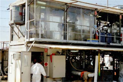
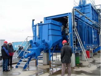
Figure 6.5.2 Facilities in containers The plant itself was planned as an escalation of a smaller pilot plant. From the beginning everything was designed to be able to fit into a mobile unit. As the construction phase went on, more and more things had to be built in the plant, and because it was designed to be mobile, everything is placed in a very small place, resulting in a very compact plant.
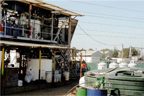
Figure 6.5.3 BCD plant April 2002, control room
Figure 6.5.4 BCD plant April 2002. Reaction tank and holding tank Maturity Smaller solids can be crushed in a ball mill before suspended into liquid and treated. The ball mill is open and also making it necessary to use personal protection equipment. The cycle time is very long, mainly due to analytical procedures. The responsible persons working with the development of the plant in Australia have done a large amount of work and improved the process. Now, in contrast to the original process, the reaction is running to an end leaving no halogenated compounds in the reaction mixture. The residual product from the reaction mixture ends up in a large horizontal tank with a small manhole in the end. When the residual product becomes cool it is difficult to get out of the tank which impacts the general working conditions significantly. Capacity Mobility Workers' health and safety Environmental evaluation Material consumption Table 6.5.9 Comparative assessment of material consumption
*1: All materials are weighted equally and no consideration has been paid to scarcity and whether the material is renewable; Energy consumption Table 6.5.10 Comparative assessment of energy consumption
The great variation depends on whether support fuel is needed or not. As an average the need for support fuel should be anticipated to be in the low end of the interval. Chemicals, emissions and elimination efficiency Table 6.5.11 Emissions and elimination efficiency
?: No data available Other issues Table 6.5.12 Other environmental issues
-: Insignificant 6.5.15 Comments from BCD. CZIn the Czech Republic, the company BCD.CZ is in the process of treating a pesticide polluted site (the "Spolana site area"). As the BCD technology occurs in various outfits based on obtainment of licences, the authors of this report have agreed to include extra information received from the CEE based BCD experience in the Czech Republic. As the technology actually is being used, we believe it is fair to include the comments which are shown in the following: "COWI has requested an understandable detailed cost breakdown, including plant and financing costs related only to the treatment of pure chemicals such as pesticides, production wastes, PCB's in their pure form etc and not to the clean up of contaminated sites. The companies which have or have had BCD licenses are not companies whose prime function is to sell chemical plant and technology packages to third party operators, but are operating companies themselves who offer primarily a package solution to particular problems. This involves erecting a plant to treat the wastes, at their own cost, with or without external engineering support, and operating the plant themselves to treat pollutants. The cost of the equipment is to a certain degree proprietary commercial data. This does NOT mean that we, BCD.CZ are unwilling to supply plant and technology. We would be prepared to consider all options within the geographical limits of our licence, but would generally prefer either to do the job as a contract, or to enter into a teaming arrangement with local entities. Everything is possible, but to date the sale of plant and technology to third parties is not included in the licensing agreements with the BCD Group. The plant described below, which treats concentrates and where needed 150 t/month pure chemicals, is built to EU safety and environmental standards, costs us US $ 4 mio. With the exception of the particular operation in the Basque country, the operations of BCD Technologies in Brisbane and the operation of S.D Meyers de Mexico, all other projects have been site remediations which included the treatment of pesticide residues which were on the particular sites as well as the treatment of contaminated soil and other matrices. Our remediation project in the Czech Republic is primarily the remediation of a complex contaminated site, included in the complete package is the decontamination and demolition of complicated buildings, the treatment of the building rubble and large quantities of surrounding soil as well as the treatment of pure chemicals, chemical waste and production residues. This last group we expect to total roughly 300 tonnes. Contaminant concentrates from treating the bulk streams in the desorber are expected to be about 3,000 tonnes, excluding aqueous condensate. However, we have extracted the cost data related to the treatment of pure chemicals and present this data. The sales price for treating highly chlorinated organic chemicals (55/65% Cl) ranges from;
The price range reflects the differences in any costs for disposal of reaction residue. The basis for this cost is: A plant with 2 lines and a combined capacity of 150 t/month pure chemicals. Recycling of carrier oil and treatment or partial treatment of reaction residue, depreciation of the plant and all installation investment over 5 years, royalties and management (1 PM and 1 accountant), raw materials and utilities, labour (4 shift system with 1 supervisor and 2 operators/shift), OHSA, disposal costs, emission control, analysis, QC/QA, repair and maintenance. Residue treatment and disposal: The BCD process requires a relatively large quantity of reaction carrier oil. Pure chemicals such as pure PCB's are added to this oil in the reactor. The limiting quantity, please note quantity not concentration, of initial PCB waste is limited only by the solids content of the mix. In the case of pure chemicals, this is NaCl, residual NaOH and any carbon from breakdown of the parent molecule. We limit the solids content to 30% in order to have efficient stirring in the reactor. The approach taken by some operators is to use cheap fuel oil and to export the mix after the reaction completion has been verified as fuel oil e.g. in a cement kiln. This is particularly attractive if the medium being treated is transformer oil contaminated with residual PCB's. Our approach is different. We use refined, sulphur free oil, such as a lube oil cut, and treat the reaction products. The carrier oil is recovered with efficiency over 80% and recycled to the reactor to be re-used. The salt and residual caustic are removed in a hot water wash, similar to de-salting operations in petroleum refining. In the case of our present job, the strong alkali solution will be used locally to neutralise acidic wastewater from other plants. Whatever process you use, somewhere you have to dispose of the salt. The solid residue remaining from pure chemicals is carbonaceous and slurried with oil that leaves as fuel, in our case to a controlled incinerator, who charges for the privilege. For this project, solid residue will be almost completely mineral; sand, clay etc. This we recycle to the thermal desorber to remove residual oil, which returns to the BCD reactor with the pollutant concentrate. Comments by COWI: 6.6 Container based incineration system (CIS)6.6.1 IntroductionThe container-based incineration system is designed for the incineration of solid, pasteous and liquid hazardous waste such as waste oil, organic solvents, paint sludge, laquers, plastic, synthetic material, rubber halogenated waste, pesticides, PCB, hospital waste and infectious waste (optional). The CIS is a small (mobile) rotary kiln and is just now being tested in Latvia and we look forward to hear about the future experiences of its performance. The capacity of the plant is 2,000-4,000 ton pr. year, depending on the bulk density and the heat value of the waste. The CIS cannot incinerate pure PCB, as the chlorine content in the waste must not exceed 10 %, subsequently only allowing a treatment capacity of 400-800 tonnes/year of e.g. PCB containing 50 % (w/w) of chlorine. However, in the mean time it can destroy other non halogenated hazardous waste. The incinerator is a turnkey installation consisting of two standard 40 ft. and one 20 ft. containers thus simplifying transportation and installation on site. The unit is complete with feeding system, rotary kiln, secondary combustion chamber, flue gas cooling system, flue gas cleaning, electrical wiring, control system, etc. The operating temperature of the rotary kiln is 1,100°C and the subsequent secondary combustion chamber ensures destruction of the organic components at a residence time of 2 seconds at 1,100°C. The flue gas cooling system consists of a quench in which the flue gas is cooled by evaporation of water before it enters a heat recovery boiler. The boiler produces hot water, which can be utilised in several ways, for example for district heating. The flue gas cleaning system is equipped with bag filter, quench and wet scrubber, which according to vendor information ensure fulfilment of the emission requirements specified in e.g. the EU Directive 94/67/EC on incineration of waste. The market platform for semi-mobile incineration units is relatively large, why it has been decided to include the one produced by Chemcontrol A/S and Soil Recovery A/S from Denmark. These companies have operational experiences from similar installations from Denmark and Malaysia. Furthermore, a cooperative agreement between the Latvia responsible authorities and the Danish vendor establishing a similar plant facility in Latvia has keen interest for this review project focussing on the CEE Region. 6.6.2 Description of the technologyChemcontrol A/S and Soil Recovery A/S have designed and constructed a mobile Container-based Incineration System (CIS), for high temperature incineration of toxic and hazardous wastes, hospital waste and other industrial wastes, designed on a modular basis to facilitate shipping and erection. Each module is completed with all pipe-works and electrical installations and during pre-assembly all connections between modules are made and the entire plant is "hot-dry" tested before deliverance meaning that all basic functions have been tested. Oil has been burned in the kiln reaching normal operation temperature. The CIS has a rotary kiln incineration system with a flue gas cleaning system, and works at an operating temperature of 1,100°C to 1,200°C in is a fully automatic and computer controlled operation. The CIS is designed for incineration of all kinds of organic hazardous wastes ranging from general industrial waste over hospital waste to highly halogenated chemical waste. It can process waste that is solid, liquid and pasteous including:
Incineration The rotary kiln system has proven especially good for hazardous waste because a rotary kiln can handle solids, solvents and gases at the same time. For municipal waste, normally all solid waste, a roasting furnace is the normal device. The functional basis for all kilns is the same and can be characterised with the 3 T's (Temperature, Time, and Turbulence). Temperature Time Turbulence Hazardous waste incineration Properly managed incineration can, in principle, destroy pesticide waste with a Destruction and Removal Efficiency (DRE) of 99.99 percent or higher. Some incinerators even claim DRE values of up to 99.99995 percent. However, the DRE is defined as DRE = Mi-Ms/Mi x 100, where Mi is the mass of a chemical fed into the destruction system during a known period of time and Ms is the mass of the chemical released in stack gases during the same period of time. The releases of chemicals via fly ash, bottom ash and scrubber water is not reported this way. A better measurement of destruction is the "Destruction Efficiency (DE)" which is defined as DE=Mi-Mo/Mi x 100, where Mi is the mass of a chemical fed into the destruction system during a known period of time and Mo is the mass of that same chemical released in stack gases, fly ash, scrubber water, bottom ash and any other incinerator residue. This principle shall also cover when reporting on the generation of products of incomplete combustion (PIC). The most famous PICs are dioxins and furans and when the emission of PICs are reported is must also cover the mass of PICs that is released in stack gases, fly ash, scrubber water, bottom ash and any other incinerator residue. Disadvantages Public perception of incineration is becoming increasingly negative due to real and perceived threats posed by incineration to the environment and public health. The main concerns are the formation of polychlorinated dibenzodioxins and polychlorinated dibenzofurans (often referred to simply as dioxins) when chlorinated waste is incinerated. Also the releases of heavy metals and dust are of concern. Dioxins, which are extremely toxic and persistent in the environment, are formed as the result of a reaction during the cooling of the stack gases. The formation of dioxins has been minimised in modern incinerators either by cooling down in boilers taking out the heat of the flue gas or by quenching off gases quickly to below 250°C and the release of dioxins, heavy metals and dust are carefully controlled by passing off gases through intensive flue gas cleaning processes. Reports of many different kinds of releases from incineration plants are in modern flue gas cleaning systems collected either in the dust filters, in the scrubber systems or in the activated carbon filters. Activated carbon filters will collect all kind of organic products, and as the activated carbon is incinerated after use, these compounds are collected and destroyed. A disadvantage though is the poor control of the residual products placed as hazardous waste on landfill, which may contain high levels of POPs and other toxic chemicals. High temperature incinerators are complex pieces of equipment, which require highly skilled personnel and constant monitoring to maintain stable operating conditions. The requirements to stable operating conditions are uniform for all reviewed technologies, but are of further importance for open-processes than for closed processes. Many studies have revealed that uncontrolled release of e.g. dioxins from incineration process can be controlled although increased risks for emissions are recognised during start-up and close-down of operation. Advantages Incineration of organic chemical waste has the following advantages:
Finally, the incineration processes at a single process destroys all organic compounds and change their dangerous chemistry radically to something less dangerous. These advantages, in combination with extensive use for municipal waste treatment and combined energy utilisation (distinct heating and electricity utilization) are the background for the very general use of incineration and have made the basis for the development of many different incineration systems. 6.6.3 Description of the plantFeeding system (1) Liquid wastes are pumped into the kiln through lance, and the continuous correct dosing of the waste is secured via the CRS-system (Control, Regulating and Supervision system). Rotary Kiln (2) Slag bath Temperature and oxygen concentration in the kiln is controlled currently by a Programmable Logic Controller (PLC) ensuring a fully automatic operation.
Figure 6.6.1 Flow diagram of CIS The secondary combustion chamber (3) Quench (4) Heat recovery boiler (5) Bag filter (6) Secondary quench (7) Wet scrubber (8) Stack 6.6.4 Description of the operationComprehensiveness Robustness The CIS system is delivered with a 2 year guarantee. A longer guarantee may be negotiated. In the system launched for e.g. Latvia, a 1-year commissioning and 2 years of guarantee related to the equipment has been agreed. Residual products
A landfill is needed to deposit these rest products. There exists analysis for dioxin of flue gas and wastewater, but the CIS has never been tested for dioxin etc. in the other rest products (slag, fly ash, sludge). 6.6.5 Plant capacityThe capacity of the plant is 2,000-4,000 ton pr. year, depending on the bulk density and the heat value of the waste. Furthermore, the waste can contain up to 2.5 % Sulphur (S) and 10 % halogen (mostly chlorine (Cl), which makes this technology more "narrow-minded" versus treatment of high content of POPs. 6.6.6 Practical experienceIn 1999, the CIS was started up in Austria at the Austrian hazardous waste treatment plant near Vienna. The CIS are used for treatment of mercury containing batteries in Austria. The organic content of the batteries are burnt in the CIS, after which the flue gas is treated to remove the mercury content. In 2000, Chemcontrol sold two CIS-plants to Kualiti Alam (concession national treatment facility for hazardous waste in Malaysia) in Malaysia for treatment of hazardous waste. Furthermore, in 2001 a CIS-test plant facility was erected at the mother company Kommunekemi A/S. In 2002, Soil Recovery A/S, another Kommunekemi subsidiary, who has taken over the business with the CIS, entered a final agreement with the Latvian Ministry of Environment setting up a plant facility during 2003/2003 with anticipated start operations in 2nd half 2004. The plant facility is co-financed by the Danish EPA and the Latvian authorities. Furthermore, the Danish EPA through its DANCEE programme has released funds for a technical assistance framework supporting the Latvian authorities complying with any national, regional and international regulation and implementation of necessary public information activities. 6.6.7 Maintenance and service requirementsTo operate the CIS incineration facility, the following support staff is necessary; blacksmiths, electricians, machine operators, laboratory personnel (internal, external), landfill operators and water cleaning operators. Furthermore, to obtain full operation of the facility, the following infrastructure is considered necessary:
Maintenance is somewhat hindered by the very compact construction of the plant. Because of the small construction many features are on one hand placed at the outside easy to go to, but on the other hand there are important features difficult to reach. However, the fact that the plant has been running already for several years in Malaysia, and 2-3 years in Austria, tells that maintenance is manageable even though there has been several problems as described later. 6.6.8 Occupational health and safetyThe most obvious occupational health problem that could be detected at the visit is situated around the hopper. The feeding is done by help of truck emptying drums down into the hopper. If there are any dusty powders, dust will appear in the working area. Apart from this, the hopper is supplied with a hood and a ventilation system that transfers any vapours into the incineration zone. Also by emptying drums with liquids into the hopper, splashes can be expected, polluting the working area and the nearby instruments. The emptying of drums into the hopper is surely a weakness of the CIS system. 6.6.9 Operational risksAn emergency stack is connected to the secondary combustion chamber, to be used if the temperature in the combustion chamber and the filter bags gets out of range. There are 3 levels of interlocking to control the system:
This emergency stack has been used rather often in the trial run, because it can be difficult to control the calories in the waste introduced into the rotary kiln. If the temperature becomes too high, it is necessary to stop the feeding of waste, close the duct to the filters, or open the emergency stack, which will cause that un-cleaned flue gas reaches the atmosphere. Furthermore, the CIS-system has had the problem that by feeding high loads of zinc compounds there have been high emissions of zinc. 6.6.10 Plant mobilisation/demobilisationThe CIS system is semi-mobile of nature. It will take 2-3 months to dismantle - move and re-locate the system. The relocation costs will estimate 20% of the initial capital costs corresponding to about 500,000 USD incl. decommissioning, transport, crane assistance, re-installation and re-commissioning. However, new installation of supply lines, planning approval etc. will mean further costs, why a general perception is that a relocation to obtain full operational mode will require additional costs equivalent to approx. 50% of the capital investment costs. A new system capable of treating about 2,500 tonnes/year cost approx. 3 million USD. The time from signing off contract to start-up operation of the CIS-system, a 1- year period must be anticipated. 6.6.11 Capacity buildingIn co-operation with Chemcontrol, Soil Recovery may submit key personnel for a period in order to assist in the day-to-day operation and handling of the incoming waste. There may be training of key staff, especially transport crew, laboratory staff, sampling personnel and plant operators. The needed capacities are available within the vendor organisation. However, the amount of these services will be designed for each contract. 6.6.12 Environmental impact of the technologyThe assessment of the environmental impacts is based on the criteria presented in Section 6.2. Materials consumption
The remainder consists of materials and items like electrical engines and cables, stainless steel and fibre glass. The amount of waste treated in the plant will be around 2,100 tonnes per year. Assuming an overall life of around 10 years of plant constructions, the consumption of construction materials will be around 0.013 kg pr. kg of waste treated. Assuming an overall recycling rate of approx. 90%, which should be considered realistic in most countries, the consumption of construction materials is reduced to <0.002 kg material pr. kg waste treated. Compared to the consumption of means of operation indicated below the consumption of construction materials should be regarded as insignificant. The main means of operation and consumption related to selected waste types are listed in Table 6.6.1 and 6.6.2. Among the minor ancillary materials consumed but not listed in Table 6.6.2 may be mentioned activated carbon used for cleaning of air emissions and TMT used for precipitation of heavy metals in the wastewater. After use, the carbon is treated in the plant parallel to other waste. Table 6.6.1 Consumption of important means of operation related to the CIS-process
*1: Waste types are characterised as follows: Of the means of operation listed in Table 6.6.1, electricity is an energy source and will be considered only as such. The diesel oil is a non-renewable resource besides that it adds to the energy consumption, as energy is being used for extraction and refining besides that diesel oil contains energy. Finally, sodium hydroxide should be regarded as a renewable resource as well as a source of energy consumption as energy is being used for extraction, preparation and refining. The material consumption for the CIS-process related to the selected waste types is presented in Table 6.6.2. Table 6.6.2 Material consumption related to the CIS-process
*1: Waste types are characterised as follows: Energy consumption The CIS-process being an incineration process typically develops excess heat that may be recovered and used for district heating and other purposes. Whether a heat recovery activity may be established or not depends on local conditions. In general, the heat output is 1 MW/hour corresponding to approx. 12 MJ/kg waste and can give rise to an income in case the heat can be utilised. As heat utilisation cannot be guarantied, the choice is made not directly to reflect such a heat recovery activity in the figures stated in Table 6.6.3. Table 6.6.3 Energy consumption of the CIS-process
*1: The energy consumption related to consumption of diesel oil is based on a figure of 46 MJ/kg gas, of which 42 MJ is the energy content and 4 MJ is the energy used for extraction and refining of gas; Chemicals, emissions, residues and elimination efficiency Table 6.6.4 Generation of emissions and residues from the CIS-process
*1: DM = dry matter Concerning the constituents in emissions and residuals from the process, the figures in Table 6.6.5 and Table 6.6.6, which relates to measurements during spring 2002 (reference to Mr. Lennart Scherman, Chemcontrol, October 2002) are anticipated to be representative for both waste types indicated. Table 6.6.5 Content of substances in emissions and residues - registered concentrations for pesticide waste
?: No data available. Table 6.6.6 Content of substances in emissions and residues - registered concentrations for mixed chemical waste
?: No data available. Using the amount of organic carbon as the measurement unit, DRE (destruction and removal efficiency) may be estimated as stated in Table 6.6.7. The data available does not allow estimation of DE (destruction efficiency). It should be noted that the general criteria on the content of TOC in the slag allows up to 2% carbon to be present, which reflects a DE value for organic carbon of 97-98%. Table 6.6.7 Assessment of DRE
?: No data available It is noted that no data on the content of dioxin in the fly-ash is available. For incineration plants, this figure is often high and must be assumed to be high unless the opposite is documented by measurements. Attention must also be paid to the fact that incineration of hazardous waste in a small unit like CIS is a process depending strongly on the heat value of the waste and therefore occasionally/potentially difficult to control. In serious cases it may be necessary to close down the process and allow flue gas to be released to the environment without being subject to flue gas cleaning. Such incidents, which are difficult to quantify, are not reflected in the figures stated above, but should not be overlooked. Other issues 6.6.13 EconomyFor the treatment of about 3,000 ton/year is needed one CIS plant including boiler and flue gas cleaning, at the costs of 2.6-3 mill. USD. Operational costs are highlighted in Table 6.6.8 below. Table 6.6.8 Break down of CIS costs per kg hazardous waste
The estimated prices include license, design, and overhead. Labour costs are of course country dependent. As has been seen from other technologies, the analytical costs are high and can comprise up to 30-40% of the project costs. The analytical costs also include 4 independent analyses per year by the authorities of dioxin, dust and other required parameters of air and water emissions. Furthermore, the hopper system of the CIS requires that the waste is fed in small pieces and as an adequate mixture of solid and liquefied waste. Fluids can not be fed in this way, and paint containers will be too big and must be shredded first. Costs of shredder system have not been included. In addition to the plant capital cost, pre-treatment and storage facility is needed for liquid, solid and pasty waste. The plant capital cost for such equipment such as shredder tanks mixer and pumps is in the range of USD 150,000 to 1,500,000, meaning that the total costs of the plant may reach 4-4.5 mill. USD and more or less double the amount paid for interest and repayment. 6.6.14 Evaluation of the CIS technologyTechnical evaluation There have been problems with sufficient oxygen content (maybe too much waste fed in) some of the stuffing boxes were un-tight, rotary kiln lining, etc. Some of the more specific problems encountered are looked upon beneath. However according to the company, these problems have been corrected and improved in the recent edition of the CIS. The hopper system This system demands that the waste is fed in small pieces and as an adequate mixture of solid and liquefied waste. Fluids cannot be fed this way.
Figure 6.6.2 The hopper of the CIS, Denmark, May 2002 The screw conveyor has been improved to avoid the waste to stick to it. When the screw conveyor is not totally tight, then gas from the incinerator can be pressed out backwards and make the content in the hopper create vapours. However, the incinerator is only allowed to be operational if the screw conveyor is covered of waste. The control box and main switches on the outside of the incinerator are placed near the hopper and easily risk getting dirty when emptying drums into the hopper. Incinerator Kiln Quench Bag house filter Special waste Maturity Versatility/robustness Capacity Mobility Worker's health and safety Environmental evaluation Material consumption Table 6.6.9 Material consumption of the CIS system
-: Insignificant Energy consumption Table 6.6.10 Energy consumption of the CIS system
*1: The large variation depends on whether support fuel is needed or not. As an average, the need for support fuel should be anticipated to be in the low end of the interval. Destruction efficiency Table 6.6.11 Emissions and elimination efficiency
?: No data available Other issues Table 6.6.12 Other environmental issues
6.7 Cement kiln (CKI)6.7.1 IntroductionA cement kiln is a kiln that slowly rotates to expose limestone, sand and clay evenly to very high temperatures (1,400-2,000oC) to make cement clinker. Organic waste can be injected into the kiln with the fuel or directly into the flame. The high temperature and long residence time (6-10 seconds) effectively oxidise the organic waste. Acid gases resulting from organo-chlorine chemicals are supposed to be mostly neutralised by the alkaline cement eliminating the need for a caustic scrubber. Only modern cement kilns with bag house filters and bypass systems can be used for pesticide incineration. Special modifications and parts are needed for injecting pesticides into the kiln, which can be costly. 6.7.2 Description of the technologyBurning of hazardous industrial wastes in cement kilns are being used for the disposal of hazardous wastes in France and Norway and a number of other European countries. The principal processes employed in making cement clinker can be broadly classified as either "wet" or "dry" depending on the method used to prepare the kiln feed. In the wet process the feed material is slurried and fed directly into the kiln. In the dry process the kiln exhaust gases are used to dry the raw meal (a mixture of limestone and other raw materials) while it is being milled. A cement kiln typically comprises a long cylinder of 50 to 150 metres, inclined slightly from the horizontal (3% to 4% gradient) which is rotated at about 1 to 6 revolutions per minute. The solid material passes down the kiln as a result of rolling and slipping as the kiln rotates. The material flows counter current to the combustion gases and fuel is fired at the lower (front) end of the kiln. Gases discharged from the kiln are normally cleaned of particulate matter by passing them through an electrostatic precipitator. Dust collected in the precipitator can be returned to the process. Kiln fuel firing systems are designed to minimise energy consumption and to provide appropriate flame shape for clinkering the raw materials. Operating conditions within the kiln are maintained and controlled by monitoring numerous plant operating parameters throughout the system. These include feed material composition, gas temperatures and gas flow rates. These parameters are used for control of feed flow rates into the unit (for raw meal and fuel) and for controlling discharge gas flows from the unit. The clinker manufacturing process starts by producing a fine powder containing strictly controlled proportions of:
When the powder is homogenised and heated to 1,450°C in the kiln, the lime molecules combine with all the silica, alumina and iron oxide molecules to form clinker. The raw materials are transformed into clinker in several stages:
The material can only form at this temperature and consequently the material must reach this temperature to make clinker. After reaching this temperature, the clinker is rapidly cooled. The clinker is finely grounded, 3% to 5% gypsum is added to control the setting rate and other additives (slag, fly-ash, limestone filler, etc.) may be introduced to form the final product.
Figure 6.7.1 Schematic diagram of a typical cement kiln At the very high temperature of the cement kiln, and with the long residence times available, high destruction efficiency is possible for scheduled wastes including POP's. The highly alkaline conditions in a cement kiln are supposed to be ideal for decomposing chlorinated organic wastes. Chlorinated liquids, chlorine and sulphur are neutralised in the form of chlorides and sulphates, however measurements shows that there is still some HCl-emission from a cement kiln burning halogenated waste. The quantities of the inorganic and mineral elements added in treating scheduled wastes are usually limited (and in general will be a small proportion of the large feed requirements of a commercial kiln), and should not adversely affect the quality of the clinker product. No liquid or solid residues requiring disposal are generated as all residues are bound within the product. In some dry and some wet cement kiln processes there is a slight concentration of heavy metal in the by-pass dust waste produced when inorganic materials are included in the scheduled waste being treated. Dust waste can be utilised as fertiliser, for liming or is dumped. Incineration Pre-treatment Flue gas cleaning However, dust emission is a big problem for many cement kilns, and as long this has not been taken under control, hazardous waste treatment in such a plant is regarded as "not immediate recommended". If any dioxins are being produced in the cooling process, it may be released hanging on the dust. Furthermore, if heavy metals are being treated they may also be found in the dust. Even HCl has been seen leaving the cement kiln via the flue gases, so emissions must be under control before treating hazardous waste in a cement kiln. Wastewater and rest products 6.7.3 Description of the plantThe treatment of hazardous waste in Norway is in fact divided between two plants i.e. NOAH who does all the pre-treatment and NORCEM the cement factory who destructs the pre-treated hazardous waste. NOAH has two plants; a pre-treatment plant for organic hazardous waste in Brevik neighbour to the NORCEM and a treatment plant for inorganic hazardous waste on the island Langoya. There is an agreement between NOAH and NORCEM regulating the economic relationship. In Brevik, NOAH has a modern high tech hazardous waste pre-treatment plant. The plant consist of an administration building, a laboratory, a storage house for received drums, a shredder system for the drums containing organic liquids and solids, a filtering system for the removal of metal from the solids, a mixing system for solid waste with wood chips, a holding tank for the solid waste mixed with solid and a tank yard for solvents. Please refer to Figure 6.7.2. All emissions are monitored and controlled. The whole area is paved with a local closed sewage system. An automatic fire extinguishing system has been erected, and they have their own fire brigade. In case of fire there is a holding system for the water used to extinguish the fire. At NORCEM the plant consists of an area for reception of bulk hazardous waste, a system of hydraulic pressures, screw and envelop conveyors, holding tanks for reception of solvents, system of lances for the introduction of the hazardous waste into the cement kiln, an electro filter to filter dust from the flue gas and a bag house filter to improve the dust filtering. 6.7.4 Description of operationNOAH
Figure 6.7.2 The shredder and waste sorting plant, Norway, August 2002 The solid waste in drums are shredded and mixed with bulk waste and then mixed with wood chips to dry up the waste. All iron in the process is removed by sieving the dried waste before the deliverance to NORCEM. Iron would be a problem in the cement production. The sieving of the waste sucked into wood chips is obviously not a problem as could have been expected. We have not been informed how the iron residues are cleaned afterwards. Hazardous fluid waste received in drums is shredded in a closed system and the metal is removed before the waste is send to a holding tank and from there to the tank yard. NOAH has 5-10 chemical experts or waste evaluators that are responsible for the reception and the evaluation and proper treatment of the waste. The ground staff at the plant does not have any special education, but they can ask for assistance from the waste evaluators in special situations. A thorough risk analysis has been made of the company, and most sensitive areas are covered by nitrogen, and mounted with gas measurement instruments.
Figure 6.7.3 Process diagram for the NOAH pre-treatment The working environment is found to be good due to the fact that all chemical processes take place in a closed environment. There is no smell of chemicals at the plant. For a more detailed process diagram, please refer to Figure 6.7.3. NORCEM NORCEM had an electro filter before the agreement with NOAH was assigned. As part of the agreement, NORCEM installed a bag house filter after the electro filter. The bag house filter covers around 1/3 of the air emission (200,000 m³/hour, whereas the remaining 100,000 m³/h is still only covered by an electro filter. A reception facility to the solid hazardous waste and a tank facility to the fluid hazardous waste were also erected. The capacity is about 500 m³ for the solid waste and 260 m³ for fluid waste. The bunker for solid hazardous waste is one of 3 equal bunkers (Figure 6.7.4) where the two others are used for bone flour and residue derived fuel (municipal waste). Underneath the bunkers is a huge hydraulic station, constructed so it possible to press the waste into a screw conveyor that is feeding an envelop conveyor belt feeding the cement kiln.
Figure 6.7.4 Hazardous waste bunker, NORCEM, Norway, August 2002 The transport to NORCEM of solid waste mixed with wood chips and al iron removed is done in open containers on a truck (500 m) and tipped into the ventilated bunker. For safety reasons, the tanks for the fluid waste were placed inside a mountain. NOAH pumps the solvents 400 m up to the tanks in the mountain. From there NORCEM pumps the solvents 400 m down. The introduction of coal, meat, animal meal, and waste oil is done through a special lance into the cement kiln. The cement kiln (dry process) is 80 m long and is regulated for the control room. The solid waste is used in the calcinations end (1,000-1,100°C) of the cement kiln, whereas the fluid waste is used in the hot end (>2,000°C). The solid waste will be led through the kiln and be treated at high temperatures too. This cement process does not produce any scrubber water and no slag. The process has unplanned stops, but as soon as this is detected, the use of hazardous waste is aborted, and because it takes several hours before the temperature is going down in the incinerator, the left-behind waste is burned before total stop for repair. One of the steering parameters is the chlorine content. According to the agreement NORCEM can feed up to 100 kg of chlorine per hour. Too much HCl in the flue gas will give production problems. As the amount of waste used per hour corresponds to about 5 tonnes, 100 kg corresponds to a Cl-content of about 2%, or at 6,500 hours to 1,300 tonnes/year of POPs containing 50% chlorine. In the solid waste, the Cl is mixed down to 1% and S to about 3%. The amount of S from the solid hazardous waste is calculated in kilo, corresponding to amount in tonnes from the limestone and is therefore not seen as a problem. Limitations 6.7.5 Plant capacityThe heat value of the mixed solid waste and the fluid waste is around 13-17 MJ/kg. About 2.5 tonnes per hour of hazardous waste is used in 6,500 operational hours corresponding to 16-17,000 ton/year at NORCEM. NOAH estimates an annual treatment capacity of 30,700 tonnes of waste based on two shifts. At present, they treat approx. 16-17,000 ton in 2,400 hours of operation. There are 28-29 full time employees at NOAH and two at NORCEM. NOAH does not receive pesticides and PCB but they can treat it. They can however not empty a PCB container. All other types of container are treatable in their shredder system. In terms of POPs treatment, this is of course a serious limitation. However, a shredder system able to shred PCB capacitors may be installed for a combined solution if necessary. 6.7.6 Practical experienceThe 3 years of practical experience from NOAH/NORCEM has not been copied yet in other parts of the world. However, in France, Holland, Belgium, United Kingdom and USA, the fuel concepts are developed where hazardous companies blend certain kinds of solvents and sell this to the cement kilns as replacement for coal firing. But this total concept for both solvents and solids developed in Norway is not seen anywhere else as far it is known. 6.7.7 Maintenance and service requirementsThe cement process has a run time of about 80-85%, including 4 yearly times of planned maintenance. The pre-treatment plant at NOAH has a crew that constant takes care of maintenance. A lot of procedures have to be followed when maintaining a hazardous waste plant and the mechanics that has to perform the maintenance must be able to read, understand and follow written instructions. To operate the facility, the following staff support is considered necessary:
Furthermore, the pre-treatment plant has service lines of electricity, water, pressure air, nitrogen, sewerage system, fire extinguishing system, sodium hydroxide and activated carbon. 6.7.8 Occupational health and safetyThe working environment is assessed as close to optimal, due to the fact that almost all chemical processes are made in closed environments. Chemicals can not to be smelled at the plant. The driving with the solid waste sucked into wood chips do not pose any problem the distance being only 300 m and the receiving bunkers are closed and well ventilated. 6.7.9 Operational risksA thorough risk analysis has been made of NOAH, and the most sensitive areas are covered by nitrogen, and mounted with gas measurement instruments. 6.7.10 Plant mobilisation/demobilisationMobilisation, demobilisation is not possible with this technology which is a combined technology. 6.7.11 Capacity buildingNORCEM/NOAH has no plans for commercial utilisation of the technology and technique. 6.7.12 Environmental impact of the technologyThe assessment of the environmental impacts is based on the previous used criteria. Materials consumption
The amount of waste treated in the plant is around 16,500 tonnes per year. Assuming an overall life of around 10 years of plant constructions, the consumption of construction materials will be in the range of 0.09 kg pr. kg of waste treated. In technical terms, most of the construction will have an effective life of 20 years or more. The real life will depend heavily on the conditions for cement manufacturing operation. Assuming an overall recycling rate of approx. 90%, which should be considered realistic in most countries, the consumption of construction materials is reduced to <0.01 kg material pr. kg waste treated. Thus consumption of construction materials should be regarded as insignificant. The means of operation includes:
It has, however, not been possible to quantify the consumption of these means of operation. The waste treated is characterised as mixed chemical waste containing around 1% chlorine and various concentrations of sulphur having a heat value of 13-17 MJ/kg. Energy consumption The heating value is in average 60% of the heating value of coal. The Cement Kiln Incineration may be rated above average or even best on the energy issue. This is due to the effective utilisation of the heat value of the waste directly as process energy. Besides that, other operations at the cement plant may hardly be influenced by the burning of mixed chemical waste. Chemicals, emissions, residues and elimination efficiency The total emission of dioxin to air in 2001 is stated at 0.199 g/year approximately corresponding to 0.1 ng/Nm³ (reference to NORCEM information on measurements by the authorities, August 2002). Assuming this figure to equal I-TEQ, the emission corresponds to approx. 12 ng I-TEQ/kg waste. As part of this emission is caused by ordinary cement manufacturing, the correct figure is <12 ng I-TEQ/kg waste. No other data relevant for assessing the content of organic substances in the emission to air and fly ash is available. It should be noted, that unless otherwise documented, it must be assumed that the fly ash from the process may contain significant quantities of dioxin. As the relevant data are not available, it is not possible to assess neither DRE (destruction and removal efficiency) nor DE (destruction efficiency) of the process. Other issues 6.7.13 EconomyNORCEM had an electro filter before the idea of using hazardous waste came up. When they started to use hazardous waste they installed a bag house filter after the electro filter. NORCEM invested 140 million NOK (app. 24 million USD) for the above mentioned facilities, whereas NOAH invested about 400 million NOK (app. 68 million USD) for the building of the total new pre-treatment plant. Table 6.7.1 outlines main economic parameters. The price of the waste treatment can be seen in the pricelist, but for chlorinated waste it is typical about 5-6,000 NOK (app. 950 USD) per ton. On the other hand, the treatment of PCB cost 35,000 NOK (6,000 USD) per ton and for pesticides, official prices are 15,000 NOK (2,500 USD) per ton. Table 6.7.1 Main costs
* Comprises 24 million USD investments in the cement kiln and 68 million USD for the hazardous waste treatment plant. Both investments are necessary for the correct treatment, but the idea is that many kinds of hazardous waste carry the economic burden, not only POPs. 6.7.14 Evaluation of the CKI technologyTechnical evaluation For the typical counter current process configuration, polluted-soils and solid waste cannot be fed into the firing end of the kiln, since they would discharge in the clinker without adequate treatment; besides, they cannot be fed into the cool end of the kiln, as the waste would volatilise and would not be adequately destroyed. When operated properly, destruction of chlorinated compounds in cement kilns can be >99.00% complete with no adverse effect on the quality of the exhaust gas. Anyway, it can be seen that NORCEM as even a very modern cement plant has an emission of 42 kg of HCl per 24 hours. And if the POPs are containing sulphur then the emission of SO2, is already over the allowed limits. However, the contribution of waste materials to the exhaust gases are relatively low given that the waste are only used as a minor supplement to the main energy or raw material stream. Furthermore, is important that the cement kiln has modern dust emission reducing equipment. Many pollutants will have a tendency to stick to the dust. NORCEM has a flue gas emission of 300,000 m³/hour and emits 8.8 kg dust per hour (~30 mg/m³) giving rise to 0.1 ng/m³ dioxin (on the limit according to EU-directive). Cement kilns are allowed to have a dust emission of 30 mg/Nm³ according to the EU-directive. As can be seen, a reduction of the dust emission would most possibly also cause a fall in the dioxin emission. For comparison, the dust emission from a hazardous waste is around 2-3 mg/m³ and must not exceed 10 mg/m³ according to the EU-directive. As it can be seen, the Norvegian solution with a company as NOAH conducting a lot of special pre-treatment makes the use of the cement kiln solution possible. The energy from the hazardous waste is used in the cement produc-tion. However, it must be remembered that liquid hazardous waste traditionally consists of polluted water, with a water content up to 90%. This kind of waste must also be treated, and that is not very wanted by the cement kilns. In Norway they come around the problem by sucking this kind of waste into wood chips, making the waste still burnable. Furthermore, the incomming waste to NOAH in general has a low water content. Water containing waste is treated elsewhere. Many of the older types of cement kilns, which are seen all over the CEE Region, are not assessed as suitable for international compliant hazardous waste treatment. Only a few of the cement kilns in developing countries meet the technical requirements that, in principle, makes them egliable for incineration of certain groups of hazardous waste including POPs. Expert advice is needed to assess whether kilns can be used and special equipment is required to inject the hazardous waste into the kiln, or if extra filters are needed, not mentioning scrubber systems etc. Such equipment is expensive and should only be installed and used under expert supervision. Furthermore, an important feature that has been complied with in Norway, but has a tendency not always to be considered, is to concentrate the work with the hazardous waste on specialists. People working in a cement plant are specialists in making cement, nobody is better than them to do that. However, they are not experts in how to treat hazardous waste. Consequently, the pre-treatment of hazardous waste shall be put in specialist hands in special designed surroundings as in NOAH in Norway. The erection of a plant facility, like the one at NOAH in Norway is expensive and estimated costs exceeds 90 million USD. The updating of the cement kiln with a bag house filter and miscellaneous additionals costed 20 million USD. Such systems must be regarded as non-applicable to the CEE Region due to total lack of affordability. Finally, the global cement industry these years is under stress for constant consolidation, which make today's ownership and eventual related investment projects (pre-treatment, etc.) vulnerable for structural change in the ownership set-up. Environmental evaluation Material consumption Table 6.7.2 Comparative assessment of material consumption
-: Insignificant Energy consumption Table 6.7.3 Comparative assessment of energy consumption
-: Insignificant Chemicals, emissions, residues and elimination efficiency It is also noted that it is rather difficult to document the environmental performance of CKI as substances and decomposition products originating from hazardous waste is strongly diluted by emissions and residues originating from raw materials for cement manufacturing. Special attention must be paid to the procedure of integrating fly ash and other flue gas cleaning residues in the final product - the cement. It is noted that many countries (e.g. Denmark) as a general policy does not accept the strategy of dilution as a way of solving the problem of disposal of residual products containing hazardous substances. Furthermore, an amount of 30-35% alternative fuel gives rise to an emission of 0.1 ng/Nm³ of dioxin or <12 ng I-TEQ/kg waste (Table 6.7.4). This is a high level compared to dedicated hazardous waste destruction plants. Reference is made to the GPCR-plant with an emission of 1.1 ng I-TEQ/kg waste and the CIS-plant with an emission of 1.3 ng I-TEQ/kg waste. Table 6.7.4 Emissions and elimination efficiency
?: No data are available: Other issues Table 6.7.5 Other environmental issues
6.8 Cyclone reactorThe main information outlined about the Russian developed cyclone reactor is extracted from the NEFCO PCB Fast Track Project - Feasibility report, February 2002. 6.8.1 IntroductionThe company JSC Tekhenergokhimprom, a privatised company of some 20 employees, with the department for concepts and design located in Moscow, Russia and with test facilities in Orekhovo-Zuevo has developed the basic technology. Their basic business is waste treatment, and hereunder the incineration of hazardous waste. They are not themselves interested in transformer handling and cleaning, but they are interested in PCB destruction and are completely open to the possibility of co-operating with a transformer cleaning company. The testing centre in Orekhovo-Zuevo for treatment of highly toxic waste was established in 1973. It started with destruction of different types of chemical waste. Already then, the technology was one of the controlled incineration with high-temperature neutralisation of the acids in gas/solid phase reactions. Similar facilities have for a long time been used to clean wastes from the pesticide industry. Formerly, Tekhenergokhimprom was a state owned company which in 1980 was nominated as the key institute for the incineration and neutralisation of solid and liquid chemical wastes as well as sludge in the RF. 6.8.2 Description of the technologyThe description is based on 4 pilot test lines for incineration of toxic waste containing organic chemicals in which chlorine, phosphorous or sulphur is a constituent. Being a test facility, the various lines are manually operated. The assessed test line includes:
The tests have been public approved by two organisations, the first one approving the technical description of the facility, and the second issuing an operating permit granted by the Moscow Health Authorities and is valid for a 3-year period (2000-2003). This permit comprises the incineration of all toxic organic substances (Russian class 1-4) covering PCB. In the beginning of the 90s it became necessary for the organisation to reorient the work from mostly research towards commercial incineration of toxic wastes from the Moscow region. Among other, also non-PCB containing transformer liquids are being incinerated here. For this, the liquid from an old transformer at a potential client is sampled and analysed for chlorine content. And if not found, the transformer is then transported to the site and emptied. In case chlorine is found, they refuse to handle the oil from that transformer. Actual projects
6.8.3 Description of cyclone processThe heart of the Cyclone Process is the incineration chamber. The one from the test installation in Orekhovo-Zuevo is shown in Figure 6.8.1. As illustrated, the name Cyclone Reactor comes from the swirl movement of the combustion gases – this same movement that ensures a high degree of turbulence and thus efficient mixing. 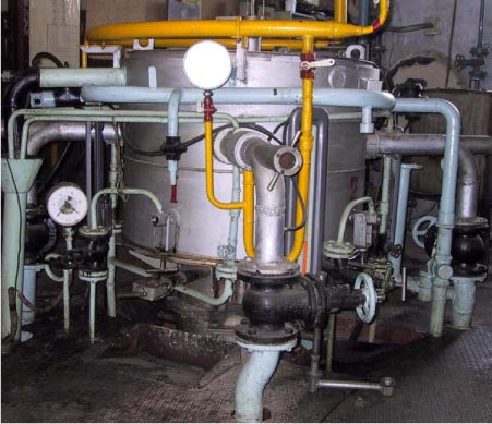
Figure 6.8.1 Brick lined top of cyclone reactor in Orekhovo-Zuevo The cyclone reactor is a vertically mounted cyclone type incinerator in which the combustion air and the fuel enter with a velocity around 100 m/s thus ensuring intimate mixing and high turbulence. The retention time here is around 0.3 seconds and the temperature 1,600-1,700°C (lining with chromium magnesite or Al2O3). The caustic solution is then added through nozzles and the temperature drops to between 1,250 and 1,400°C, and in the subsequent brick-lined afterburner is ensured another 1.7 seconds of retention time. The main principles (process diagram) of the entire installation are shown below.
Figure 6.8.2 Process flow diagram for the cyclone process The cyclone reactor technology contains a high-temperature gas/solid phase reaction. This takes place between the caustic (dissolved Na2CO3 or NaOH or Ca(OH)2) and the acid gases formed by the incineration of S-, P- or Cl-containing organic substances. In all cases, the reaction products come out as a powder of salts, retained in bag filters as opposed to the other processes where more or less polluted brine is the waste product. Because it is introduced into the hot combustion zone, liquid spent caustic solutions may be used as a cheap source of sodium hydroxide. If not available, a solution is prepared from purchased chemicals. The primary reaction is the gas phase reaction (simplified) where practically all hydrochloric acid reacts with the caustic:
The remaining caustic reacts with carbon dioxide:
This core of the method was patented in Russia, but the patent was not maintained and is thus no longer valid, and the system has been copied in Germany and in Scotland. With certain chemicals, the salts are actually melting and collecting on the surface of the incineration chamber, and subsequently flow out from the bottom. But in the case of PCB, it is to be expected that NaCl powder will travel through the system to be collected in the bag filter. The exact temperatures and injection points depend on the product to be incinerated. In the case of PCB, the design would be with the support fuel in the top of the combustion cyclone and the PCB intimately pre-mixed with the caustic solution a little further down. The need for support fuel depends on the material to be incinerated. In the combustion process it is important to have a surplus of steam to avoid any tendency for soot formation from incinerating of the cyclic organic components (the shift reaction will ensure the formation of CO instead). Steam is present from the natural gas incinerated as well as from the subsequent injection of NaOH solution. With certain cyclic organic chemicals it is necessary to add more in the form of water; but this is not required for the combustion of PCB. Downstream of the afterburner, the hot gases enter a quench tower, where the temperature is taken down to approx. 200°C (possible range 160-220°C) the exact level being determined by the bag filter operation. At these temperatures the salts solidify from the gas phase, forming a fine powder. High temperature fibres are then used in the bag filter, thus allowing the flue gas to stay well clear of lower temperatures where the salts would become sticky due to the high humidity in the flue gas. During earlier tests, the company Taifun made 3-5 analyses for dioxins in this powder, but even traces could not be detected, and further analyses were therefore abandoned. In the flue gas, many measurements of dioxins have been made, and these results have shown values below 0.1 ng/Nm³. Experience with difficult chemicals Much research work is behind the curve presented in this article. So, if the incineration process may be controlled well enough, then traditional incineration is a fine way to dispose of such toxic chlorinated organic components. It is this work, on the incineration of components very similar to PCB that gives reason to believe, that the test will prove PCB incineration to be very efficient and satisfactory in a CEE developed context. 6.8.4 Description of operationOne of the potentially important features of the process is the lining with insulating bricks. In Korea, fine quality bricks made of 95% pure corundum exists which makes them very resistant to heating and cooling. In Russia, only an 85% quality is available. The practice in Korea to start up and shut down the unit every day should therefore not be attempted with a Russian-made installation. Here, continuous operation should be foreseen as much as possible. A PCB collection tank should hold at least a week's consumption before the unit is started up. Hereafter the unit should be operated continuously until the tanks is empty. Such mode of operation requires 5 shifts with 2-3 operators in each shift. The cyclone reactor facility is not very complicated to operate. The four important parameters to master and control are:
As a supplement to the above, the CO level is monitored closely, mainly because combustion of CO is slower than that of dioxins. Experience has shown that if CO is below 5 mg/m³, the dioxin level is below 0.1 ng/m³. For this reason there shall be at least approx. 3% oxygen in the flue gas (excess air in the combustion). Furthermore, it has been experienced that dioxin levels rise (a fivefold number has been measured, or 0.5 ng/m³) during start-up and shutdown of the unit. For this reason, waste should only be injected, once the unit is heated up and operating. In Korea, among many other types of hazardous waste, three types of chlorinated chemicals (methylene chloride/chloroform, carbon tetrachloride, and chlorobenzene) have been incinerated in the cyclone reactor without any traces of dioxins measured in the flue gas. 6.8.5 Evaluation of the cyclone reactor plantIn general, the process is well proven and mature, but not for the specific application of PCB destruction. Like any other elimination technologies, the cyclone reactor has positive and negative effects. Advantages
Disadvantages
Technical evaluation Downstream of the hot zone, all equipment may be made of plain carbon steel. Maturity of technology Incineration is the best known of all technologies. The traditional criterion for PCB incineration with minimum 1,100°C and min. 2 seconds retention time is complied with. Together with practical experience with incineration of other halogenated components – additional research is carried out at present. Tentative results show that operating improvements are obtainable by the Cyclone Reactor with caustic injection in the hot zone. Any of the following caustic liquids may be used – also those that might be polluted with organic matter: NaOH, Na2CO3, KOH, K2CO3 (the two carbonates are the least expensive, and therefore normally chosen, when fresh chemicals are to be purchased). Versatility/robustness Capacity Utility requirements have – on a preliminary basis been determined to:
More accurate estimates will be available after specific tests related to actual waste. Mobility of facility Workers health and safety Environmental evaluation Airborne emissions Noise Waterborne emissions Waste generation It is therefore expected that these ashes may be disposed of in a properly conceived waste dumpsite. This however, still has to be proven. Energy conservation Compliance with emission norms Prohibitive features 6.9 Comparative evaluation of the 4 reviewed POPs elimination technology plants6.9.1 Environmental evaluationThe environmental comparative assessment of the 4 reviewed elimination technologies presented in the previous chapters (the cyclone incinerator excluded) focuses on the following issues:
Consumptions of materials Still, the comparison regarding construction materials is interesting indicating a trend consistent with the figure shown by consumption of means of operation, namely that the CIS solution allows for a higher flow of waste materials through the system than the chemical decomposition systems. The CIS system thus obtains a higher material efficiency and deserves to be rated best in this regard. The GPCR technology equals the CIS technology on the comparison of material consumption. The BCD system on the other hand stands out as having an out standing high consumption of mineral oil used in the operation placing this solution un-disputably as the worst in this regard. The CKI solution has to be ranked low due to the lack of precise data. Table 6.9.1 Comparative assessment of material consumption
-: Insignificant Energy consumption Comparing the CIS system with the GPCR system, CIS is assessed slightly better as the energy consumption in most cases should be expected to be lower than for the GPCR system. Generally, the better the heat value of the waste, the better performance of CIS compared to GPCR and vice versa. Again the BCD system is indisputably ranked lowest due to outstanding high energy requirements coming from consumption of electricity as well as the carrier oil. Table 6.9.2 Comparative assessment of energy consumption
-: Insignificant Chemicals, emissions, residues and elimination efficiency The BCD process is rated second primarily based on the values for DE and DRE. The process suffers from a high content of chloride in the residual product, and no data on emission of dioxin to air is available from the destruction (by incineration) of the residual product. It is however recognised that all experience with incineration based systems points at quantities of dioxin in fly ash and other flue gas cleaning residues. Thus, there is no reason for assuming the CIS and the CKI processes to perform better than BCD on the issue of dioxin. The CIS is rated low. The DRE value for organic carbon and low dioxin emission to air should although be recognised. However, as stated above, the dioxin content in flue gas residues should be expected to be high and the overall destruction efficiency remains to be proven considering that up to 2% carbon is allowed in the slag. Attention must also be paid to the fact that incineration of hazardous waste in a small unit like CIS is a process depending strongly on the heat value of the waste and therefore occasionally/potentially difficult to control. In serious cases it may be necessary to close down the process and allow flue gas to be released to the environment without being subject to flue gas cleaning. Such incidents, which are difficult to quantify, are tried reflected in the figures below, and should not be overlooked. The Cement Kiln Incineration is also rated low due to lack of data. It is noted that it is rather difficult to document the environmental performance of CKI as substances and decomposition products originating from hazardous waste destruction are diluted in emissions and residues originating from raw materials from the cement manufacturing. In this case, special attention must be paid to the procedure of integrating fly ash and other flue gas cleaning residues in the final product - the cement. Until better knowledge has been developed, it must be assumed that this procedure in reality is a way of "hiding" dioxin in cement and spread it into the society and the environment as a consumer product. Table 6.9.3 Comparative assessment of emissions and elimination efficiency
?: No data available Other issues As the Cement Kiln Incineration process eliminates waste products by integrating these into the final product - the cement - this process may be ranked highest. However, as discussed above it is debatable whether this way of disposing of fly ash etc should be considered acceptable. The GPCR process distinguishes itself from the BCB and CIS processes by not generating any hazardous waste that requires further treatment or special disposal. The amount of solid waste is very low, while the amount of wastewater hardly can be regarded as a problem, considering that is cleaned by an activated carbon filter. For these reasons, the GPCR process is ranked "highest" of the remaining processes. Regarding the CIS process, the fly ash, the slag and the quench residues are likely to be disposed of as hazardous waste to a special landfill due to the content of dioxin as well as other pollutants indicating that there is a need for landfill capacity. Thus the CIS process is ranked below the GPCR process. The BCD process presents its own special set of problems, as it generates a relatively high quantity of residual product, which is composed of carrier oil together with remains of NaOH and a significant content of chlorine from the decomposed substances. Uncontrolled burning of this product could lead to significant dioxin formation and appropriate disposal must include treatment on a facility specialised in treatment of liquid chemical waste. For this reason, the BCD process is also ranked below the GPCR-process (Table 6.9.4). Table 6.9.4 Other environmental issues
0?: No data are available, but could be 0. 6.9.2 Technical evaluationCapacity Table 6.9.5 Capacity
Comprehensiveness All the plants can treat most types of containers and most types of wastes, although they all have their special compounds they have to avoid or minimise. Table 6.9.6 outlines the performed assessment. Table 6.9.6 Comprehensiveness
Maintenance Table 6.9.7 Maintenance
Transfer of know-how Table 6.9.8 highlights the assessment of transfer of know-how abilities, which for a CEE context is of major importance, due to a relatively weak, highly complex industrial sector. Table 6.9.8 Transfer of know-how
Special supply lines Table 6.9.9 Special supply lines
Residual products Table 6.9.10 Residual products under control
Occupational health Table 6.9.11 Occupational health
Operational risk Table 6.9.12 Operational risk
Mobility Table 6.9.13 Mobility
6.10 Summary and discussionIn Table 6.10.1 please find the overall rating scheme as a conclusive result of the performed detailed review based on 21 selected review criteria covering technical, environmental and economic issues. Table 6.10.1 Overall rating of the review of selected POP elimination technologies
6.10.1 Critical assumptionIt has to be emphasised that Table 6.10.1 is entirely subjective and the scheme should only be read together with the total text of this chapter. However, the scoring and the weighing of scores are based on our best estimate. Furthermore, who can decide what is most important: technology, environment or economy? What about the missing issues? In fact it can be proven mathematically that this way of comparing things is not possible. Nevertheless, the scheme hopefully makes it easier for relevant CEE key resources to discuss and overview the extensive amount of relevant information in a single glance with the risks of oversimplifying the complexity of the technology related review. Evaluation We have evaluated the technologies against each other. The cyclone reactor though, has not been visited and examined by the present authors, but we rely on information received from other COWI employers working closely with this technology. However, due to lack of exact knowledge on key areas of economy and environmental performance, it has been decided not to give any evaluation of that plant. As outlined in Table 6.10.1, the technical, environmental and economic criteria were reviewed in detail. Technical performance Generally, the 3 technologies are equal in technical performance. The BCD plant on the contrary came out below average in the technical evaluation, mostly due to low capacity, weak performance of comprehensiveness, and weaker occupational health control. Environmental performance Economic performance Evaluation summary The three plants in the first group are more or less equal in the environmental and the technical evaluation, but are diverting in the economical part. The capital investment costs are higher for the GCPR than for the comparable CIS. The cement kiln is in that respect in a class by itself. On the other hand, if one uses an existing up-to date cement kiln, then the treatment costs per tonne are comparable. The general conclusion of the performed detailed review outlines that based on global market survey and filtration of incoming information on a number of merging technologies, two technologies seems to have the potential as optional POPs waste eliminators in the CEE Region, the GPCR and CIS technologies. This is further underlined by the fact that the CIS technology has scheduled operational activities ongoing in Latvia (Latvia is also in the recent DG-Environment report on Obsolete Pesticides Status in the candidate countries grouped in category 1 - countries which are far advanced in their efforts solving the obsolete pesticides problems). In parallel, the GPCR technology is in progress of scheduled activities in the Slovak Republic via a basket funded project (Slovak government, private industry, GEF funds, etc.). Both technologies wish to utilise these market platform options as demonstration objects for further exploitation. As described earlier in the report, the market in the CEE Region is not at present open for commercially operated POPs waste elimination technologies. However, through these two "ice-breaking" initiatives, a new era within OP/POPs elimination is hopefully initiated leading to more broad solutions on hazardous waste in general in a specific CEE context complying with not only national priorities, but also with international binding environment protocols and conventions related to POPs and related chemicals.
|
|||||||||||||||||||||||||||||||||||||||||||||||||||||||||||||||||||||||||||||||||||||||||||||||||||||||||||||||||||||||||||||||||||||||||||||||||||||||||||||||||||||||||||||||||||||||||||||||||||||||||||||||||||||||||||||||||||||||||||||||||||||||||||||||||||||||||||||||||||||||||||||||||||||||||||||||||||||||||||||||||||||||||||||||||||||||||||||||||||||||||||||||||||||||||||||||||||||||||||||||||||||||||||||||||||||||||||||||||||||||||||||||||||||||||||||||||||||||||||||||||||||||||||||||||||||||||||||||||||||||||||||||||||||||||||||||||||||||||||||||||||||||||||||||||||||||||||||||||||||||||||||||||||||||||||||||||||||||||||||||||||||||||||||||||||||||||||||||||||||||||||||||||||||||||||||||||||||||||||||||||||||||||||||||||||||||||||||||||||||||||||||||||||||||||||||||||||||||||||||||||||||||||||||||||||||||||||||||||||||||||||||||||||||||||||||||||||||||||||||||||||||||||||||||||||||||||||||||||||||||||||||||||||||||||||||||||||||||||||||||||||||||||||||||||||||||||||||||||||||||