|
| Front page | | Contents | | Back | | Printing instructions |
Autonomous Weeder for Christmas Trees – Basic Development and Tests

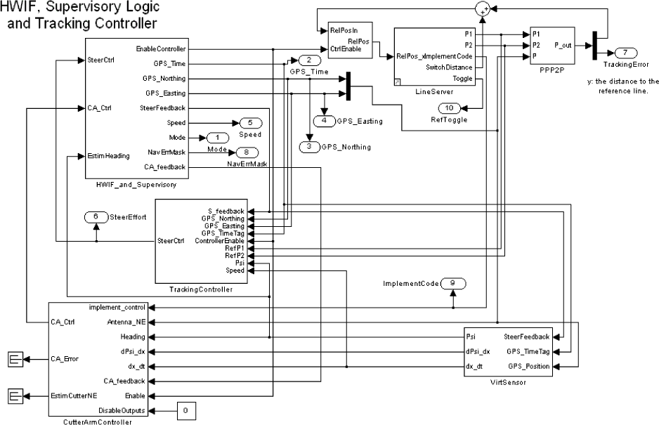
Fig. 5.12. Top-level Simulink control diagram. The round-edged boxes are output ports, which are used to provide values to scopes and to the operation log. The big boxes are subsystems as described in the following:
HWIF_and_Supervisory contains the hardware interface blocks (i.e. the “hardware drivers”) and the supervisory logic (start modes, Navigation mode, Joystick mode), along with protection blocks (i.e.
thermal protection of actuators based on usage-time)
VirtSensor is a virtual sensor block which estimates the current heading and speed of the vehicle based on the GPS history
LineServer provides the geographical reference (i.e. it contains the route plan). It provides two points, and steps through the route plan based on distance feedback. This block can be used both in line-tracking mode (use both points) and point-tracking mode (only use point P2)
TrackingController is the block used in navigation mode (when the vehicle moves autonomously) to calculate the appropriate pulses for control of the steering actuator/steering angle to get the vehicle to track the planned route
CutterArmController deals with the pull-in and release operation of the cutter arm (in order to avoid collision with trees), based on the current implement command, GPS readings, estimated heading etc. This block (or a parallel one) should also handle the cutter clutch (but this is currently handled elsewhere).
| Front page | | Contents | | Back | | Printing instructions |
Version 1.0 November 2005, © Danish Environmental Protection Agency
|