|
2 Layout of refrigeration systems
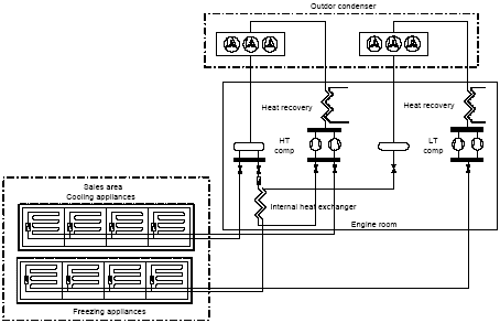
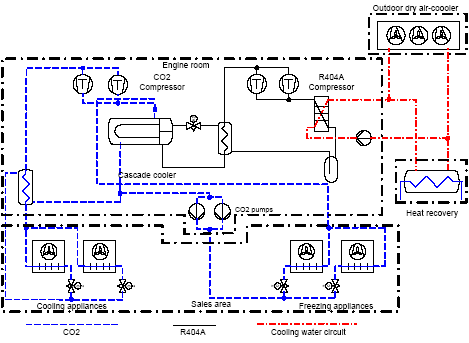
2.1 Conventional refrigeration systemsThe ISO-2 and ISO-4 systems are conventional systems of the parallel type with separate circuits for cooling and freezing and one-stage compression. The refrigerant used is R404A. Direct dry-expansion evaporation takes place in the cooling and freezing appliances and condensation takes place in air-cooled condensers mounted on the roof of the building. ISO-4 has a heat exchanger between the cooling and freezing circuits, but it was used during the period of measurement. Furthermore, in this system heat exchangers are mounted for heat recovery from super-heating and condensation. Figure 2.1 shows the construction, in principle. 2.2 Cascade refrigeration systemsThe ISO-1 and ISO-3 systems are the newly developed cascade systems. CO2 is used in both cooling and freezing appliances. Dry expansion is used in freezing appliances. CO2 compressors compress the evaporated CO2 to the pressure in the cooling circuit. Flooded evaporators with pump circulation are used in the cooling appliances. In the cascade cooler evaporating R404A is used to condense the CO2 vapour. Compressors compress the R404A to the condensation pressure and the R404A vapour condensates in a water-cooled condenser. The cooling water gives off the condensation heat to the surrounding air in dry-coolers placed on the roof. ISO-1 has a heat recovering heat exchanger, which delivers all heating to the shop. Figure 2.2 shows the principle layout of the cascade system.
Figure 2.1. Layout of the ISOI-2 and ISO-4 systems
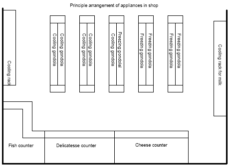
Figure 2.2. Layout of the ISOI-1 and ISO-3 systems. 2.3 Layout of refrigeration section in shopAll of the four plants are similar, in principle, as to the location of the refrigeration appliances in the shop. Figure 2.3 below illustrates the layout principle.
Figure 2.3. Layout principle for refrigeration appliances in shop. 2.4 System sizesThe sizes of the four systems are shown in table 2.1 below.
Table 2.1. System sizes Table 2.1 shows that the four systems are different in size, both in absolute terms and in terms of relative size of the different elements. All systems have pulse-width modulated control valves on all evaporators.
|


