Modern WindShips
Phase 2
Table of Contents
2. Project Strategy
Background
Strategy for Phase 2
Definitions
3. Rig Design
The Difference between a Traditional Sailing Ship and a Modern WindShip
Traditional Sailing Ships
Former WindShip Projects
The Rig of the WindShip - Phase 1
Brainstorming and New Alternatives
Alternatives to Sailcloth
CFD Calculations
4. The High-Lift Wing Mast
High-Lift Alternatives
Choosing a Rig
Wind Tunnel Tests
Results and Conclusion
The Performance of the Sail Mast Compared with the Wing mast
Relation between Performance and Price
Conclusion
5. Detailed Rig Design
Safety and Reliability
Behaviour of the Wing Mast in the Survival Mode
Turning of the Entire Mast
Turning of the Flaps.
Alternative I
Alternative II
Alternative III
Alternative IV – The Final Choice
Turning of the Four Horizontal Shafts
Fixing the Rotating Sections in a Vertical Position
Fixing the Flap to the Slat in the Folded-Up Position
Fastening of the Slats
High Lift Profile, Choice of Materials
Material Choice for the High Lift Profiles, Conclusion
Material Choice for the Mast
Material Choice for the Mast, Conclusion
Material Properties
Steel Material
Fibre Composite Properties
Core Material Properties
Structural Putty/Glue
6. Design Loads
Rules, Regulations, Standards, and Other Sources of Information
Short Background on Design Wind Load
Wind Speed Calculations
Wind Pressures
Ship’s Movements
Wind Speeds Updated with Actual Weather Statistics
Loads from Wind Tunnel Measurements of Single Rig
Dynamic Load
Individual Member Forces.
Acceleration Loads
Ice Loads
Sea Water Pressures
Other Loads
Design Loads, Summary
Factors of Safety
7. Strength Calculations using FEM
Scope of Work
Mast
Mast Foot
Flap
Buckling
Geometry used in FEM Calculations
Mast
Flap
Loads and Boundary Conditions
Mast
Flap
Results from FEM
Mast, Results
Mast Eigen-Frequency
Mast FE-model, Conclusion
Flap, Results
FE-Model of Flap Conclusion
Price and Weight Calculation
Summary and Conclusion regarding the Structural Design of the Wing mast
Loads
Weight
FEM Analysis
Computer Animation
8. Hull Design
Design of the Above-Water Hull
Tests Performed on the Hull
Wind Tunnel Tests of Above-Water Hull with Rig
Note on the Wind Tunnel Tests of Sails
The Hull Configuration Below the Waterline.
Rudder and Propulsion Systems
Propulsion Redundancy
Balancing the WindShip
WindShip Stability
Wind Tunnel Tests of Underwater Hull shapes
Tested Bow Types
The Four Tested Underwater Hull Configurations
Test Procedure
The Test Conclusions Summarised
Static Force Measurements of the Hull in Towing Tank
Model Description and Test Set-Up.
Test Conditions
Appendages
Summary and Conclusions from the Towing Tank Tests
PMM Tests
Speed, Drift and Heel
Speed, Drift, Rudder and Heel
Dynamic Course Stability
9. Simulations
Introduction
Assumptions and Restrictions
Results from the VPP
Simulations of Combined Propeller and Wind Forces
Polar Diagrams and Input to Weather Route Optimisation
Summary and Conclusion, using the VPP.
Notes on the Propulsion System, VPP and Weather Routing
Weather Routing
Assumptions and Restrictions
Trade Patterns
Calculations
Results
Weather Routing, Conclusion
10. Feasibility Study
Introduction
Background
Choice of Vessel Type
Route Selection
The Product Carrier
Fuel consumption of the Modern WindShip.
Comparison with a Conventional Ship
Assumptions
Scope of Analysis
Conclusion
Comments on the Mærsk Broker Study
The Impact of Bunker Prices
Lessons to be Learned
On the Choice of Vessels
On Trade patterns, Speed, Fuel Consumption and Productivity
Conclusion
11. Environmental issues
Fuel Savings and Emissions
Suitable Trades and Cargoes
New Regulations
12. Future Work and Improvements
Improvements of the Efficiency of the Rig
Reducing the Price of the Rig
Conclusion on Rig Optimisation
The Superstructure, Air Drag Improvements
Possible Improvements under the Waterline
Other Aspects
Computer Control System
Minor Items in the WindShip Design Still to be Considered
Planning of Future Work
13. Summary and Conclusion
Summary
Conclusion
14. References
Addresses:
Software
15. Index & Tables
Index of Figures
Index of Tables
List of Equations
Appendix 1. Drawings
Drawing no. 1: General Arrangement
Drawing no. 2: Central Steel Mast and Mast Foot
Drawing no. 3: Hydraulics
Drawing no. 4: Fibreglass Panels
Appendix 2. Ship
resistance, Theory and Background
Theory
Planer Motion Mechanism (PMM) Tests
Pure Yaw
Principles of Motion Generation
Speed Loss in Waves
Wave Spectrum
Added Resistance due to Waves
WindShip Speed Loss due to Waves
Appendix 3. Material choice,
background
Steel
Aluminium
Space-frame/Fabric
Composites
Aluminium
Fibre Composites, Fibre Material
Appendix 4. Wind speed
calculations
Survival condition
Full sail condition
Appendix
5. Calculation of Ship Motions and Accelerations
According to DN Volume 1, Pt. 3, Ch. 1, Sec. 4
Ship design factors given from the ship designers:
Surge, sway/yaw and heave accelerations: {B300}
Roll motion and acceleration: {B400}
Pitch motion and acceleration: {B500}
Combined vertical acceleration: {B600}
Combined transverse acceleration: {B700}
Combined longitudinal acceleration: {B800}
Combination between acceleration in different directions
Vertical and transverse force: {C500}
Vertical and longitudinal force:
Appendix 6
Calculation of the Dynamic Gust Factor , Cdyn
According to "Snö och vindlast", Chapter 3:322
Ship design factors given from the ship
designers:
Dynamic gust factor, Cdyn
Reynolds number
Appendix 7. Wind Pressure Calculations
Appendix 8. Determination of Individual Forces on each Wing mast Member
Appendix 9. Price and Weight Calculation for the Wing mast.
Appendix 10. Fuel Consumption on the Atlantic and Indian-Pacific Trade Patterns
Appendix 11. Polar diagrams from DMI/SL.
AbstractThis report presents the findings of the modern WindShip project, phase 2. The project is funded through the Danish Environmental Protection Agency, acting on behalf of the former Danish Council for Recycling and Lesser Polluting Technology.
In the previous phase 1 of the project a broad background on historical WindShips was summarised and a proposal for a new type of Wind Ship was drafted. Building on the experiences from phase 1, the second phase of the project focuses on:
Detailed design of the rig. A new rig concept is developed, using high lift profiles with movable flaps. On a central rotating high tensile steel mast sandwich profiles acting as slats and flaps are hinged on horizontal axes. The mechanical construction is covered in some detail, indicating how the mast profiles are turned, locked etc.
Realistic simulations based on measured and simulated performance. Measurements include wind tunnel as well as towing tank tests. Simulations are performed using a velocity prediction programme (VPP) developed specifically for the modern WindShip. Weather routing based on real weather statistics is performed as well as finite element modelling (FEM). A computer simulation of the modern WindShip sailing is also included, but not covered in the report.
Economical feasibility study. A commercial comparison between existing product carriers and the economical performance of the modern WindShip is performed. The comparison uses existing trade routes and patterns, drawing from the weather routing performed above, to calculate with high precision the fuel consumption of a modern WindShip.
A product carrier is chosen as design study object in the economical analysis. The product carrier is selected since such a vessel of the same size as the modern WindShip, approximately 50.000 dwt, are common. Two trade patterns are chosen as representative for product carrier traffic, one mainly in the Atlantic region, the other in the Indian-Pacific region. The economical study also investigates the effects of varying the bunker oil price, and the average speed of the ship.
Results from strength calculations (FEM) show that the overall scantlings of the mast are in accordance with leading classification societies, such as DNV. Polar diagrams are plotted using the velocity prediction programme, showing that the modern WindShip reaches 13 knots sailing speed already at about 9 m/s of true wind at 100°. Weather routing shows large variations in fuel consumption, depending on route, direction and time of year.
The economical analysis shows that on average the modern WindShip is approximately 10% less economical than a "normal" product carrier. There is a large fuel consumption penalty in sailing at 13 knots with the modern WindShip, as the engine arrangement is not chosen for these speeds, and normally winds are not strong enough on some of the selected routes to drive the ship at that average required speed. Lowering the average speed has positive effects on both the fuel consumption and the required freight rate per day.
Proposals for further optimisation are put forward.
1. IntroductionThe WindShip project was initiated in 1995 when the Danish Ministry of Environment and Energy granted funding for Consulting Naval Architects and Marine Engineers Knud E. Hansen A/S to investigate the feasibility of adding sail assisted power to propel commercial ships. The complete project was subdivided into several phases; the current report is the result of phase 2.
In phase 1, which was finished in November 1996, a broad background of different projects involving WindShips were investigated. The report described the possibilities of a new type of WindShip with a length of about 200 m and a dead weight of 50.000 tonnes. The proposed WindShip was compared to conventional ships, and it was concluded that at an increased overall transportation cost of approx. 10% a WindShip was economically feasible. The work resulted in a report: "Modern WindShips - Phase 1" which was published at the end of 1996, see Ref. 1.
These preliminary findings were so encouraging that at end of 1997, Pelmatic Knud E. Hansen A/S forwarded an application for a second phase of the WindShip-project to the Danish Environmental Protection Agency, acting on behalf of the former Danish Council for Recycling and Lesser Polluting Technology. Funding for the second phase was granted in mid 1998 and the work started in October the same year. In this phase a more detailed design was carried out. The present report summarises the findings.
A steering committee had already been formed during phase 1 and the members of this committee, with a few changes, have followed the project into phase 2. The committee consisted of professionals with expertise in the different areas concerning WindShip.
| Mr. Svend Otto Ott, Danish Environmental Protection Agency, Chairman. | |
| Mr. K. Mandrup, Danish Energy Agency. | |
| Mr.Peter Lauridsen, Senior Ship Suveyor, Danish Maritime Authority. | |
| Capt. Ole P. Nielsen, Danish Maritime Authority. | |
| Mr. Kim Henriksen, Senior Naval Architect, Danish Maritime Institute. | |
| Capt. Steen Stender Petersen, The Baltic and International Maritime Conference – BIMCO. | |
| Mr. Henrik Søderlund, M.Sc., Technical Manager, North Sails A/S. | |
| Capt. Jens V. Bloch, Maritime Consultant. |
Representatives from the Danish Shipowners’ Association and the Association of Danish Shipbuilders were invited to participate in the steering committee’s meetings as observers.
The Danish Maritime Institute (subsequently called DMI/SL) carried out important parts of the investigation in close co-operation with Pelmatic Knud E. Hansen A/S. Specifically all the wind tunnel measurements, towing tank tests and developing of a velocity prediction programme were performed here.
The Danish Meteorological Institute (subsequently called DMI/meteo), has also been playing an important role in the project, supplying a vast number of weather data for specified routes and performing the weather routing, thus allowing calculations on the fuel-consumption to be performed.
These, with other data about WindShip construction- and running-costs, were then transferred to Mærsk Broker K/S, who has carried out an economic analysis-programme, comparing the economy of a WindShip with that of a conventional vessel.
The strategy followed during phase 2 of the project has removed many uncertain factors regarding the performance and economics of modern WindShips. We believe the results found were realistic and well founded.
Finally, we take the opportunity to thank our project-partners, members of the steering committee and our own staff involved for their interest and participation in the project.
Copenhagen, December 1999.
Pelmatic Knud E. Hansen A/S
2. Project StrategyBackground
Strategy for Phase 2
Definitions
Background
At regular intervals during the last 30 years attempts to exploit the wind energy for reducing the fuel consumption of ships have been made, but because of low oil prices and the increasingly higher efficiency of modern diesel engines none of these attempts have proven economically profitable. The rising environmental consciousness in the latest years combined with the success story of the modern windmills has once again breathed new life into the ideas of developing a modern wind ship. With the findings from phase 1 of the project at hand a strategy for designing the modern WindShip was developed.
Strategy for Phase 2
For the design work in phase 2, Pelmatic Knud E. Hansen chose the following strategy:
1) Choice of rig design:
| The difference between a traditional sailing ship and windships. | |
| Traditional sailing ships. | |
| Former ideas for a windship rig. | |
| The rig design of the windship - phase 1. |
1.1) Brainstorming:
| CFD calculations of rig alternatives. | |
| Wind tunnel tests of one or two of the alternatives. | |
| Final choice of rig. |
2) Wind tunnel tests of above-water hull with rig.
3) Choice of under-water hull and propulsion devices.
4) Static force measurements of the windship’s hull in towing tank (PMM tests).
5) Velocity prediction based on the results from the wind tunnel tests of the above-water hull and the static force measurements of the under-water hull.
6) Route simulation based on the results from the velocity prediction and statistical wind data for 3 years on 6 routes world-wide.
7) Detailed rig design:
| Decision on design loads based on wind statistics. | |
| Structural design and choice of materials. | |
| FEM (finite element method) strength calculation and optimisation of the rig. | |
| Detailed design of rig manoeuvring components. | |
| Price and weight calculation. |
8) Economical feasibility study based on the route simulation results and the calculated rig price.
The strategy outlined above indicated the need to:
| Design a better rig system than the one obtained in phase 1, incorporating higher lift and less sail area. | |
| Investigate the hull lines and appendages to get good manoeuvrability and low resistance. | |
| Develop a Velocity Prediction Program (VPP) using the Planar Motion Mechanism tests (PMM) and wind tunnel measurements in order to predict ship speed depending of installed power, wind speed and wind direction. | |
| Perform weather routing and calculate realistic data regarding fuel consumption on a specified route. | |
| Make a commercial comparison on each chosen route with a conventional ship. | |
| Visualise of the WindShip rig using 3D CAD systems. |
This strategy has removed many uncertain factors from the project, therefore the results in phase 2 are considered to be well founded, reliable and realistic.
Definitions
In the text of this report the following phrases and symbols have been used, see Figure 1 below:
---
Figure 1. Definitions used in the report.
The most often used English phrases can be found in Table 1 below.
The absolute wind |
= |
The direction of the wind in relation to the sea surface. |
The apparent wind |
= |
The direction of the wind in relation to the moving ship. |
Ship’s heading |
= |
The direction the ship’s centre line points. |
The leeway |
= |
The ship’s direction through the water. |
Drift angle |
= |
The angle between the ship’s heading and the leeway. |
The cord |
= |
A straight line from the leading edge of the sail or wing to the trailing edge. |
The angle of attack or angle of incidence |
= |
The angle between the cord of a sail or the centre line of a symmetrical steel mast and the apparent wind. |
Upwind |
= |
Sailing with the apparent wind from a forward direction. |
Reaching |
= |
Sailing with the wind from the side (about 90° to the ship’s centre line). |
Running |
= |
Sailing with the apparent wind from an afterward direction. |
Lift |
= |
The force generated by the sail or wing perpendicular to the apparent wind. |
Drag |
= |
The force generated by the sail or wing in the direction of the apparent wind. |
Stem |
= |
A fixed size mass (batch) loaded on product carriers, often 25-, 35- or 40.000 tonnes. |
HFO |
= |
Heavy Fuel Oil, heavy, cheap oil used at sea, high contents of pollutants. |
MDO |
= |
Marine Diesel Oil, lighter, more expensive oil used when in port, "cleaner". |
Table 1. English phrases, definition
The ship’s courses in relation to the apparent wind have been denoted as follows, see Figure 2:
---
Figure 2. Wind direction names.
The aerodynamic forces "lift" and "drag" have been defined as follows, see Figure 3:
---
Figure 3. Lift, drag etc,. definition of terms.
The lift and drag forces vary directly with the density of the air, the sail or wing area and the square of the wind’s speed. It is accordingly convenient to express these forces in terms of non-dimensional coefficients that are functions primarily of the attitude of the sail or wing.
The lift force "L" and the drag force "D" (in N) are given by the following expressions:
| L = ˝ r V2 S CL | Equation 1 | |
| D = ˝ r V2 S CD | Equation 2 |
Where:
| r | = |
density of the air (1.21 kg/m3 at 20°C and 1013 mbar) |
| V | = |
velocity of the air in m/s |
| S | = |
area of the sail or wing in m2 |
| CL | = |
lift coefficient |
| CD | = |
drag coefficient |
The Difference between a Traditional Sailing Ship and a Modern WindShip
Traditional Sailing Ships
Former WindShip Projects
The Rig of the WindShip - Phase 1
Brainstorming and New Alternatives
Alternatives to Sailcloth
CFD Calculations
The WindShip rig is a relatively advanced construction, incorporating sandwich panels, hydraulic steering, etc which will be described in detail in the following sections.
The Difference between a Traditional Sailing Ship and a Modern WindShip
The rigs of traditional sailing ships were "children of their age". The design was based on the following principles:
- A traditional sailing ship reaches a certain speed determined by the speed and direction of the wind - no more, no less - as additional engine power is not used.
- The use of sailcloth requires a certain margin for the wind’s angle of incidence as the shape of the sail is generated by the wind pressure.
- The size of each single sail must be small enough to be handled by human power.
- The ship must be in yawing balance as the rudder is the only steering device.
- The rig design must be based on wood, iron and natural fibre ropes and sailcloth.
A modern WindShip differs from traditional ships in many areas.
As additional engine power will be used in most cases to reach a certain speed the angle of apparent wind will be shifted forward. This means that a rig for a WindShip must be better optimised for sailing upwind than the rig of a traditional sailing ship.
As fixed panels may be used in a WindShip instead of sailcloth a much wider range of angles of incidence can be utilised, see Figure 4 below.
---
Figure 4. Range of angle of incidence
Hydraulics and winches can substitute human power.
The ship does not have to be completely balanced (see chapter 8, section "Balancing the WindShip" below) as the propeller power can counterbalance the yawing moment. See also Figure 5 below.
---
Figure 5. Modern WindShip balanced with thrusters and rudder.
High tech materials as fibreglass, kevlar, carbon fibres, aluminium and high tensile steel may be used in a modern WindShip to make rig designs possible that were difficult to imagine just a few years ago.
Traditionally two types of rigs were commonly used: The square rig and the fore-and-aft rigs, see Figure 6.
---
Figure 6. Traditional sailing ships rig types.
The major and important difference between these two types is that the main sails of the square rig were symmetrical in relation to the mast and thus did not have a specific leading or trailing edge. The sails of the fore-and-aft rig however, had an asymmetrical sail profile with the greatest depth towards the leading edge. This profile was better suited for sailing upwind.
The square rig was the dominating rig for the large sailing ships. This type of rig presented the best solution of its age for a large rig that could be handled by human power, but from an aerodynamic point of view it was rather ineffective, especially when sailing upwind. The pressure difference between the leeward and windward sides of the sails was equalised through the horizontal slots between the individual sail, thus reducing the efficiency of the entire rig considerably. Apart from that the profile of the sails were far from optimal - completely flat at the upper edge and closing too much at the trailing end of the lower edge, see Figure 7.
---
Figure 7. Traditional square rig.
The maximum lift coefficient CL of a square rig was only 0.8 to 0.9.
The fore-and-aft rigs were dominated by the gaff rig. This type of rig used in smaller ships was considerably better from an aerodynamic point of view. A lift coefficient of 1.2 could be obtained.
Former WindShip Projects
Former attempts to design a rig for a windship can be divided into two major philosophies:
- Modern versions of the square or gaff rig, but with improvements in detail. Sail cloth and steel masts were normally used.
- More innovative solutions such as airfoils, foldable hard panels, rotors, etc.
The different former WindShip projects were discussed in detail in the report: Modern WindShips – phase 1, see Ref. 1. Some of the ideas are shown in Figure 8 & Figure 9 below.
Figure 8. Look here please.
Figure 8. Different rig types, reproduced from WindShip report phase 1. Originals by Peter Schenzle.
Figure 9. Look here please.
Figure 9. Coefficients for different rig types. Reproduced from WindShip report phase 1. Originals by Peter Schenzle.
The Rig of the WindShip - Phase 1
When starting the design work for a modern WindShip rig the following requirements were formulated:
| Must be handled automatically without requiring more crew. | |
| Must not interfere with the cargo handling. | |
| Must not jeopardise the safety of the vessel. | |
| Must be steady and reliable with a minimum of maintenance. | |
| Must be suitable for navigation upwind as the power from the propellers will shift the apparent wind forward. | |
| The air draught of the rig above a reasonable ballast water line must not be more than 60 m for passage of bridges. | |
| Must be reasonably easy to retrofit on existing ships. |
The rig system chosen in Phase 1 is shown in Figure 10 below.
Figure 10. Look here please.
Figure 10. The rig type chosen in phase 1 of the WindShip project.
The ship was equipped with a modern incarnation of the so-called "lugger" rig, having a certain resemblance to the rigs used in the traditional Chinese junks. Six self-staying pole masts were fitted in port side of the vessel for the sake of load handling and aerodynamics. Each mast was carrying a hoistable crane-type arm reaching to the ships centre line. A sail of approximately 1650 square metres was stretched between this arm and a boom positioned at the deck level.
This rig had many advantages but also a few drawbacks. One of the problems was stretching the lugger sail in an efficient way. Another problem was the wind resistance of the round pole mast when the sails were reefed. To overcome these problems it became clear that the steel mast should be an active part of the sailplane.
Brainstorming and New Alternatives
One of the first ideas that came up in the WindShip project was an U-shaped steel mast carrying a rather traditional sail on the trailing edge, see figure Figure 11.
Figure 11. Look here please
Figure 11. Brain storming, first idea.
The sail was equipped with shaped full-length battens. In the forward 1/3 of the batten length the sailcloth was double. Additional softer battens were fitted on both sides so that the 3 battens constituted a 3-fork. Air bags were fitted between the battens giving the total sail a very smooth and aerodynamic shape when the windward airbag was inflated, the leeward deflated.
One of the problems with this design was that the length of the battens was about 24 metres, making transportation of the sails rather difficult. The sails would have to be manufactured in horizontal panels and assembled on the location around the sail battens. If the width of the sail could be reduced to max 13.5 metres it would be possible to transport the sail complete, ready made from the manufacturer with boom, battens etc. in a 48 foot container.
Consequently, the next alternative was to use a broader symmetrical steel mast. A rig having a total area of 720 m2 and a max width of the sail of 13.5 m was developed. Of this area the mast alone made up for 300 m2, corresponding to 42% of the total area. As the mast was much wider than the previous design, air bags were no longer needed, simplifying the rig. The mast was self staying and rotating, see Figure 12 below.
---
Figure 12. Brainstorming, second idea.
Modern sailcloth has one major problem when used in conjunction with modern WindShips, it deteriorates due to sun radiation. The estimated lifetime for a modern Wind Ship sail is max. two years. This means that 15 sets of sails will be needed during the ship’s lifetime of typically 30 years.
From modern windmills we know, that the estimated lifetime of the wings is at least 25 years. Switching from sailcloth to fibreglass panels might therefore be economically beneficial in the end.
In order to obtain the highest possible efficiency of a rig the profile must be asymmetrical. This requirement is automatically met with a traditional sail, but if asymmetrical fibreglass panels were used a system for shifting the profile from one side to the other had to be invented.
One of the ideas was to make a wing sail with a well-known airfoil profile. NACA 63-412 was chosen. The profile was cut in 3 vertical pieces; an asymmetrical trailing edge of around 61% of the chord length, a symmetrical centre part of 14% and an asymmetrical leading edge of 25%. The asymmetrical trailing- and leading edges were divided into 4 horizontal sections. Each section was suspended in a vertical slewing bearing at the centre line of the section. See Figure 13 below.
Figure 13. Look here please
Figure 13. High lift wing mast, stackable single profile.
By turning the 4 sections 180° around a horizontal axis the asymmetric profile was shifted from one side to the other. In order to reduce the area in severe wind conditions the bearings were fitted on vertical tracks from the bottom of the central mast to the top. Reefing could be done by turning one or more sections to a horizontal position, stack them on the deck and lower the remaining sections to the top of the stack.
CFD Calculations
In order to study the efficiency of an airfoil compared to a traditional sail, CFD (Computational Fluid Dynamics) calculations of three alternatives were performed at the Danish Maritime Institute (DMI/SL), see Ref. 3. The first alternative was to combine the broad steel mast and the 13.5 m wide sail. The other two alternatives were the NACA 63-412 wing mast profile and a slightly modified profile with a little more depth, see Figure 14.
---
Figure 14. The three types of profiles used for CFD calculations.
The calculations were conducted at an angle of attack (a ) of 1°, 5° and 9°. The mast and sail combination proved to be the best with a lift coefficient CL of 1.4 at an angle of incidence of 9°. The airfoil had a max. CL of about 1.15, calculated at the same angle. However, in both cases the curve of the lift coefficient had not reached its maximum at 9°, so higher values at higher angles of incidence must be expected. Pressure distributions can be seen in Figure 15 to Figure 17, below.
Figure 15. Profile 1, pressure distribution at a =9°.
---
Figure 16. Profile 2, pressure distribution at a =9°.
---
Figure 17. Profile 3, pressure distribution at a =9°.
---
Extrapolating the obtained CL values of the combined steel mast/sail combination from a = 9° to a = 13° we get a CL of approximately 1.7. This corresponds well to the measurements performed later, see Ref. 4 and chapter 4 in this report.
The main reason for the difference in lift between the profiles was the different profile depths (camber). The depth of the mast / sail combination was about 12% of the chord length while the depth of the airfoil was only about 7%. The airfoil was designed for aeroplanes and not for WindShips.
An aircraft airfoil will at typical aircraft cruising speed produce more than sufficient lift. The task for an aircraft engineer is thus to develop an airfoil that gives minimum drag at low angles of attack. It is only during the start and landing phases that an aircraft needs to utilise the maximum lift coefficient.
For a sailing ship this is not the case. It is only in very high winds that it is necessary to reduce the available lift. Typically, at the WindShip’s cruising speed the task is to achieve the highest possible lift. A high-lift profile with more depth was therefore developed.
4. The High-Lift Wing Mast
High-Lift Alternatives
Choosing a Rig
Wind Tunnel Tests
Results and Conclusion
The Performance of the Sail Mast Compared with the Wing mast
Relation between Performance and Price
Conclusion
Aeroplanes need to increase the lift of the wings during landing and take off. For this purpose a slat is protruded from the leading edge of the wings and one or two flaps from the trailing edge. Small air slots are thereby created between the wing and the slat / flaps.
The idea is to prevent separation by directing air from the lower side of the wing to the upper side through backward-directed slots, thus adding kinetic energy to the low-energy boundary layer on the upper side of the wing.
The slot in front of the flap will delay turbulent separation over the flap. The slot aft of the slat will prevent permanent laminar separation over the forward portion of the wing. This lead to a new idea: The high-lift wing mast, see Figure 18 below.
---
Figure 18. The high lift wing mast.
The mast consisted of the following main parts:
| A load carrying symmetrical central mast. | |
| An asymmetrical trailing edge of the central mast. | |
| An asymmetrical leading edge of the central mast. | |
| An asymmetrical flap hinged at the trailing edge. | |
| An asymmetrical slat fixed to the leading edge. |
The principle for shifting the profile from side to side was adopted from the NACA 63-412 wing mast. All the asymmetrical parts were divided into 4 horizontal sections. A horizontal shaft through the central mast coupled the trailing- and leading edges to each other. The profile was shifted from side to side by turning these 4 shafts 180° .
The height of the wing mast was 43.1 m and the cord length with the flaps in their normal working-positions was 20.6 m, giving a total active sail area of about 890 m2.
High-Lift Alternatives
Increasing the lift of a wing by boundary layer control can be done in many different ways. Two methods are described below in more detail:
| Backward-directed blowing slots with air supplied by a blower is an alternative to the kind of slots used in the high-lift wing mast. | |
| The kinetic energy of the layers of air close to the upper surface of a wing can also be increased by removing low-energy air through suction slots or a porous surface. |
Figure 19 shows a NACA 641A212 wing section with a leading edge slat, a suction slot in the upper surface of the wing and a double-slotted flap at the trailing edge. This combination of high-lift devices gives a maximum lift coefficient of nearly 4.0.
---
Figure 19. Boundary layer suction principle. Reproduced from Ref. 27.
Very thick wing sections with large leading-edge radii and suction slots may have lift coefficients of over 5.0 but at much higher drag coefficients than the thin sections, see Figure 20 below.
---
Figure 20. Thick profile lift coefficient, with boundary layer suction. Reproduced from Ref. 27.
Although active suction or blowing by fans might improve the lift, the fans need energy, require maintenance, and they are not free of charge. The conclusion was to use a thin high-lift wing profile without blowers.
Choosing a Rig
Among the alternatives, Pelmatic Knud E. Hansen chose to proceed with, the two most promising for further wind tunnel tests. The first alternative was the combination of a steel mast and sailcloth - hereafter called "the sail mast". The second alternative was the high-lift wing mast - hereafter called "the wing mast".
Wind Tunnel Tests
The wind tunnel tests of the two alternatives were conducted in a closed circuit tunnel at the Danish Maritime Institute with models in scale 1:125. See Figure 21 below.
---
Figure 21. Mast sail and Wing Mast wind tunnel models.
The tests and the results were described in details in Ref. 4 "Report No.1, Single Rig Performance". The sail mast used for the test had a fixed sail profile. The wing mast had a movable slat and flap to optimise the position in relation to the centre mast, the width of the air slots and the total depth of the profile, see Figure 21. Using CFD to determine the properties of high lift profiles is not recommended. The most reliable results still come from wind tunnel measurements.
Because of the limited test budget the masts were manufactured of a relatively soft plastic material. The wing mast was a little too flexible causing some vibrations and mast bending during testing. The wind speed in the tunnel thus had to be limited to about 30 m/s for the sail mast and 25 m/s for the wing mast.
The scaling factor used when performing wind tunnel tests is referred to as the Reynolds number. The Re-number is defined as follows:
Re : Reynolds number : ![]() Equation 3
Equation 3
where:
r = density of air [kg/m3]
U = mean wind velocity [m/s]
c = cord length [m]
m = viscosity of air (1.789*10-5 [kg/m/s] at 20°C and 1013mbar).
When testing a profile in the wind tunnel the profile often has to be scaled down to fit inside the tunnel cross-section. As mentioned above, to obtain the same Re-number the wind speed in the wind tunnel should be increased. This was however not possible due to model limitations mentioned above. Instead a number of tests were performed running the wind tunnel at increasing speeds. At a certain speed the measured difference between two consecutive runs was small. The achieved Re-number was then considered sufficient. This procedure was performed at DMI/SL before the testing began, and the results were therefore deemed trustworthy.
At an angle of attack between 10 and 13° the maximum lift coefficient CL of the sail / mast combination was measured to 1.7 with a corresponding drag coefficient CD of 0.3.
If a slat was fitted on the leading edge the lift coefficient could be increased to 2.0, but at the same time the drag was doubled. The results for the wing mast were CL = 3.0 and CD = 1.0 at angles of incidence in relation to the central mast between 15 and 23° . A peak CL of nearly 3.2 was reached at a = 21° .
The conclusion was that the wing mast showed considerably higher lift coefficients than the sail mast, but also higher values of drag. The lift curves for the wing mast had wider peaks making it less sensitive to changes in the wind’s angle of incidence. The peak values generally occurred at larger angles of incidence than for the sail mast.
When sailing upwind (as close to the wind as possible) the relation between lift and drag is very important. A profile with less lift but also little drag could be better than a high lift profile with considerable drag, see Figure 22 below.
---
Figure 22. Lift and drag compared when sailing upwind.
At other courses with wind coming more from the aft the importance of the drag is gradually decreased until sailing at reaching and running where only one thing really counts; maximum lift.
The Performance of the Sail Mast Compared with the Wing mast
The area of the wing mast is S = 890 m2, the lift coefficient CL = 3.1, the drag coefficient CD = 1.0. The corresponding values for the sail mast are: S = 720 m2, CL = 1.7 and CD = 0.3.
For the wing mast the product S * CL = 2759 and S * CD = 890. The corresponding values for the sail mast are: S * CL = 1224 and S * CD = 216.
Figure 23 below shows these values plotted for an angle of the apparent wind of 30°.
---
Figure 23. Performance comparison between the two different rig types.
Even at this very small angle the propulsion force from one wing mast is 1.44 times the force from one sail mast. At larger angles the importance of the drag is gradually decreased so that the advantage of the wing mast is correspondingly increased.
Table 2 below shows the force relation (propulsion force from one wing mast divided by the force from one sail mast) at different angles of the apparent wind.
Angle of the apparent wind in relation to the ship’s heading |
Relation |
30° |
1.44 |
45° |
1.85 |
60° |
2.04 |
75° |
2.15 |
90° |
2.25 |
105° |
2.33 |
120° |
2.42 |
Table 2.Performance comparison between a wing mast and a sail mast.
Table 2 shows that even at upwind courses the wing mast is considerably better than the sail mast. At reaching and running the advantages are huge and it will take more than two sail masts to substitute one wing mast.
The higher drift force of the high-lift wing mast at upwind courses will give a higher drift angle, but within the relevant small angles of drift (around 2°) this will not increase the hull resistance significantly.
Relation between Performance and Price
For a WindShip the important thing is not just pure performance but the best possible performance in relation to price. In addition, the handling and maintenance costs are major factors in the total picture. The wing mast is more expensive than the sail mast. It has more moving parts and hydraulic components. The fibreglass panels are also more expensive than the sailcloth. The calculated price for a complete wing mast with hydraulics, slewing bearing at the deck, reinforcements in the ship etc. is about 7 million DKK, see Appendix 9. The price for a sail mast without sail but with slewing bearing, boom, reinforcements in the ship etc. is estimated to about 3.5 million DKK.
The price for 15 sets of sail = 15 * 420 m2 * 1000 DKK/m2 = DKK 6.300.000,- giving a total price for one sail mast including sails for 30 years of nearly 10 million DKK. Even if the sails could be produced in large industrial scale at a price of 500 DKK/m2 the total price for one mast during 30 years would be about 6.7 million which is about the same as the price for one wing mast. It is worth noting that it would take two sail masts to substitute one wing mast.
The fibreglass panels and the structure of the wing mast may also be optimised and simplified in such a way that a price reduction of 15-20% would be realistic.
Conclusion
Based on the wind tunnel tests with one single mast and the price estimation, Pelmatic Knud E. Hansen chose to proceed with the wing mast for further tests. However, it should be noted that not all combinations and possibilities were investigated, due to limited resources. The selected wing mast was considered to provide a reliable light weight structure requiring low maintenance.
5. Detailed Rig Design
Safety and Reliability
Behaviour of the Wing Mast in the Survival Mode
Turning of the Entire Mast
Turning of the Flaps.
Alternative I
Alternative II
Alternative III
Alternative IV – The Final Choice
Turning of the Four Horizontal Shafts
Fixing the Rotating Sections in a Vertical Position
Fixing the Flap to the Slat in the Folded-Up Position
Fastening of the Slats
High Lift Profile, Choice of Materials
Material Choice for the High Lift Profiles, Conclusion
Material Choice for the Mast
Material Choice for the Mast, Conclusion
Material Properties
Steel Material
Fibre Composite Properties
Core Material Properties
Structural Putty/Glue
In the following section detailed design of the mast will be described. Only the more complicated items were considered.
Safety and Reliability
The basic requirements to the rig with regards to safety and reliability were as follows:
- Any defect or malfunction must never jeopardise the safety of the vessel or the crew.
- Any maintenance work or inspection of hydraulics or equipment must be done from a safe working position.
- In the "survival mode" the mast must be able to withstand the worst possible wind conditions.
- The mast must not under any circumstances generate forces or heeling moments that are dangerous for the stability of the vessel or will jeopardise the manoeuvring possibilities.
- The mast must be flexible and be able to give away and relieve the wind pressure in case of sudden strong gusts.
To fulfil these requirements the following design characteristics were incorporated:
- The aft flaps were hinged at their leading edges and controlled by a hydraulic turning mechanism, designed to let the flaps give way and relieve the wind pressure at wind speeds exceeding 20 m/s. The ability to automatically reduce the lift in a smooth and non dramatic way is one of the clear benefits of the wing mast, compared with the sail mast where the sail will start to flatter.
- The mast could be reefed by folding one or more of the flaps up against the central mast. The "closed" mast was still an airfoil with a reasonable lift coefficient and with a very little drag. See Figure 24 below.
- The entire most would turn itself into the wind eye like a flag at wind speeds exceeding 25 m/s. In this "survival mode" the wind resistance from the mast will be very small because of the aerodynamic shape and the small projected area.
The different turning mechanisms are described in detail in the following sections.
---
Figure 24. Wing mast folded together.
Behaviour of the Wing Mast in the Survival Mode
A wing mast that is turned into the wind eye to survive strong winds has advantages but also some drawbacks compared with a sail mast.
The wing will remain steady because of the hard panels whereas the sail will start flapping strongly. On the other hand, if the direction of the wind starts changing quickly the sail will be flapping from side to side but without generating a lift.
The wing mast may start oscillating from side to side as lift is generated in alternating directions. To avoid this, it may be necessary to incorporate airbrakes in the upper part of the mast to reduce the lift generated. Small flaps that are extended perpendicular from the mast in the forward part would act as brakes. Airbrakes are well known from aeroplanes where they are used to reduce the lift of the wings once the plane has set its wheels on the ground.
If airbrakes are necessary at all is difficult to determine from wind tunnel test. If or when a large-scale test mast is built, the necessity of the brakes should be tested.
Turning of the Entire Mast
The entire mast is fitted on a slewing bearing on top of the weather deck. The inside of the bearing is fitted with a gear rim enabling the mast to be turned by two slow-turning hydraulic drives.
Alternatively, the mast could be suspended at the weather deck and the tank top in simple slide bearings but this arrangement would be more expensive, decrease the loading capacity and increase the weight.
The wind tunnel tests were conducted with vertical masts turning around a vertical axis positioned at the quarter length of the cord from the leading edge.
As mentioned, the mast should position itself in the wind eye like a flag in case of extremely strong wind or hydraulic or electrical failure. Thus the aerodynamic centre of the mast must be aft of the turning centre of the slewing bearing, even with the flaps reefed against the central mast.
Assuming that the aerodynamic centre is positioned on the quarter length of the cord of the reefed mast it was necessary to tilt the mast 4° aftwards and place the central steel mast at the aft end of the slewing bearing.
A slewing bearing with a raceway diameter of about 6 m would be sufficient to take-up the loads from the mast. However, a raceway diameter of 7.4 m has been chosen because of the following reasons:
- Large safety factor
- The larger diameter of the gear rim would lower the tooth pressure so that only 2 slow turning drives were necessary to turn the mast. (A raceway of 6 meters would require 3 motors.)
- If a raceway of 6 meters was chosen the mast would have to be fitted 6° aftwards instead of only 4° to position the aerodynamic centre of the mast aft of the turning centre.
The two slow turning hydraulic motors are bypassed by pressure relieve valves so that the entire mast will turn into the winds eye at a certain well-defined moment.
In order to relieve the gear wheels and the gear rim when the mast is not turning it would be advisable to fit a braking system e.g. a disc brace. This braking system should be designed not to prevent the mast from turning in case of a strong wind gust.
The mast has two working positions – open and closed. The largest turning moment of the motors is required when the flaps are open.
From the wind tunnel tests of a single wing mast the forces in the mast foot were available as coefficients (see Ref. 4).
| CL = Lift coefficient. | |
| CD = Drag coefficient. | |
| CN = Yawning moment around a vertical axis positioned on the quarter length of the cord. |
Multiplying these coefficients by the dynamic pressure:
![]() , where:
, where:
v = the wind speed and r = the density of the air » 1.25 [kg/m3] and the relevant area will give the forces in N.
The forces in the slewing bearing were calculated using an Excel spread sheet. See Figure 25.
---
---
Figure 25. Mast foot calculation.
FN is the vertical force from the mast without acceleration allowance.
The friction coefficient of the slewing bearing is µ = 0.001.
The result of the calculation shows that two slow turning drives, each with a turning moment of 1.1´ 10.5 Nm, are necessary if the diameter at the gear rim is 7.4 m and the diameter of the gear wheel of each drive is 0.5 m. (Slow turning drivers, like the transmission-less Hägglund Viking 84-38000, are suitable for this purpose.)
Note that a wind speed of 25 m/s and a lift coefficient of 3.1 is used in the calculations although the flaps starts to give way for the wind pressure already at 20 m/s.
Turning of the Flaps.
Apart from the safety benefits turning and controlling the flaps have other advantages:
- The profile depth of the mast could be trimmed flatter when sailing upwind than when reaching and running. Especially, when sailing upwind it is beneficial to use a deep profile at the foremost mast and gradually flatter profiles for the aft masts.
- A certain twist could be established taking the difference in the direction of the apparent wind over the height of the mast into account.
The turning centre of the flaps had to be positioned close to the leading edge of the flaps as the air slot between the flap and the asymmetrical trailing edge of the central mast was to remain constant while turning the flap.
The high lift coefficient of the flap combined with the forward turning centre resulted in a large turning moment. The moment is calculated in Appendix 8. However, the best way to find the required moment would have been to measure it in the wind tunnel. We believe that the calculated moment is on the conservative side resulting in turning mechanisms that is too powerful.
As the flaps should automatically give way and relieve the wind pressure at a certain well-defined wind limit, a turning mechanism with a constant turning moment was desirable. Several alternatives were investigated all concentrating on creating a hydraulic constant-moment turning mechanism by-passed by a pressure relief valve.
The first suggestion was to use a modified rotary vane steering gear, like the gears typically used for turning the rudders on ships, see Figure 26.
---
Figure 26. Rotary vane engine flap turning mechanism.
A constant release moment was easy to establish simply by by-passing the hydraulics by a pressure relief valve.
Normally this type of gear has two (or three) internal blades to increase the turning moment, but as this gear should be able to turn the flap 200°, only one blade was possible. Consulting the company "Ulstein Tenfjord" (see Ref. 44) indicated that modification of a standard unit was possible.
The advantage of using a rotary vane gear was the well-proven high reliability, but the drawback was the high weight of about 6 tonnes per unit and it’s relatively high price. Moreover, the gear was positioned outside the mast so that maintenance and inspection was not as easy as desirable.
The conclusion was to investigate other alternatives although we still believe that a rotary vane gear custom-designed for this special purpose including all bearings for the flap would be a good, simple and very reliable solution.
The next alternative was to turn the flaps by means of large gear rims fitted at the top and bottom of the flaps.
The rims should be turned by gear wheels fitted on a common vertical shaft inside the asymmetrical trailing edge of the central mast. A slow turning hydraulic drive turned the shaft. See Figure 27.
---
Figure 27. Gear rim flap turning mechanism.
In order to reduce the tooth pressure the radius of the gear rim should be as large as possible was necessary. (2.4 m was the maximum.)
- When turning the 4 flap-sections around the horizontal shafts the flaps describes 4 circles on top of each other when looking from the front of the mast.
- Despite the large diameter of the gear rims the tooth pressure is still very high. This could course unacceptable wear and tear as effective lubrication was difficult to establish.
As the gear rims with their large diameters should remain inside the circles they have to be positioned about 500 mm from the top and the bottom of the flap. This will complicate the design of the asymmetrical trailing edges of the central mast.
The flaps could also be turned by a hydraulic cylinder and link mechanism, see Figure 28.
---
Figure 28. Flap turning through link mechanism.
The disadvantage of this solution was that the turning moment was not constant, so it was difficult to create the constant release moment required for safety reasons.
Some kind of electronics would have to be incorporated to control the relief valve.
Alternative IV – The Final Choice
The final choice was to create a constant moment by a standard hydraulic cylinder acting on the flap via a girth around a disc integrated in the flap, see Figure 29
---
Figure 29. Hydraulic flap mechanism.
The maximum force in the girth was about 30 tonnes. A girth made of high-tech materials with a width of 300 mm and a thickness of 10 mm, was sufficient. (A girth called "Twin-Path" by Slingmax, see Ref. 46 could be used. The girth is slightly flexible, which will reduce the stresses in the structure in case of sudden gusts.
Apart from the flexibility a permanent elongation of the girth of about 2% must be expected over time. To control this flexibility and to avoid uncontrolled swinging of the flap a spring-loaded counter girth was fitted. The hydraulic cylinder should have a safe working load of 60 t. The cylinder and the rollers etc. were fitted inside the ø800 mm hollow shaft for easy access, see Figure 29 above.
The horizontal shaft consists of 2 parts joined together around a gear wheel used for turning the shaft. In both ends the shaft was suspended in "Thordon XL"-bearings (see Ref. 40) - a relatively cheap nylon material that absorbs shocks and does not need lubrication.
The flaps were suspended in "Thordon"-bearings like the horizontal shafts.
A hollow stainless steel shaft running inside a filament wound fibreglass tube was fitted inside the flaps from top to bottom, see Appendix 1.
The fibreglass tube was permanently bonded inside the flaps, whereas the steel pipe was exchangeable and fastened only in one end of the fibreglass tube. The outside diameter of the steel pipe was constant, but the wall thickness was increased in way of the bearings. The advantages of this system were multiple:
| A direct, stiff load path was created from the flap turning disc where the girth load is applied to the flap bearings. | |
| No fastening of metal structures inside the composite flap. Typically such fastenings are bolted, and inspection and spanning would be difficult. | |
| The shaft was easy to replace. |
The drawback of course is the weight. In the finite element analysis (see section "7. Strength Calculations using FEM" on page *) the steel shaft was not included, as it did not prove necessary for the overall strength of the flap. A lighter solution using locally fastened bearings should be investigated in a future project.
Turning of the Four Horizontal Shafts
As the horizontal shafts are positioned in the centre of each rotating section the moment required to turn the shafts is relatively small. A simple mechanism consisting of a gear rim around the shaft and a vertical toothed bar activated by a standard hydraulic cylinder was chosen. See Appendix 1. Drawings and Figure 30 below.
---
Figure 30. Rotating the high lift wing profiles.
Fixing the Rotating Sections in a Vertical Position
In order to relieve the turning mechanism for the horizontal shafts hydraulic cylinders are fitted in the aft part of the central mast to lock the trailing edge. Two cylinders are fitted each moving two synchronised locking pins. See Appendix 1. Drawings.
Fixing the Flap to the Slat in the Folded-Up Position
When the flaps are folded to the mast they must be locked. For this purpose an automatic locking device based on a spring-mounted fork fitted on the slat has been developed. See Appendix 1. Drawings.
The locking mechanism consists of a tong that turns around a fixed point. The tong is loaded by a spring mounted to hold the tong in open or closed position. When the wing is being folded together, the wing tip will touch the tong and force it to turn and eventually lock the tip.
To ensure that the tong is in the right position, capable of catching the approaching tip, a lace that will force the tong into the receiving position is fitted.
Fastening of the Slats
Both the asymmetrical leading edges of the centre mast and the slats are made of fibreglass sandwich.
The leading edge is bolted to a flange on the horizontal shaft. The slat is fitted to the leading edge by 3 horizontal streamline-shaped "bridges" (NACA-profiles). The upper and lover bridges are relatively thin profiles made of fibreglass on a foam core. The middle bridge is a little thicker and contains a fibreglass protruded hollow tube, glued into the core material, to give room for the hydraulic cylinder manoeuvring the flaps.
Figure 31 below shows the different fibreglass panels.
Figure 31: look here please
Figure 31. Fibre-glass panels
High Lift Profile, Choice of Materials
A short background on steel, aluminium, composite materials and sandwich constriction can be found in Appendix 3.
Material Choice for the High Lift Profiles, Conclusion
The high lift profiles are to be built of composite materials. They are described in more detail below.
Outer Shell
The outer shell of the high lift profile is a fibreglass sandwich construction. Face sheets of 2 mm quasi-isotropic polyester/fibreglass material were joined with a 30 mm Divinycell H80 core.
Internal Structure
The structure inside the high lift profiles is essentially a stiffened shell structure. Since the outer shells were sandwich panels, having a higher stiffness than single skin fibreglass panels, the distance between the internal stiffeners could be rather large. This reduced the overall weight of the structure. The internal stiffeners were of sandwich construction, using balsa core material where necessary instead of foam, to better resist buckling.
Aft End
The aft end of the high lift profile is narrow. A massive sandwich construction was therefore chosen in this region, using up to 90 mm thickness H60 Divinycell core and 2 mm face sheets.
External References
The construction of the flap, and other composite components, was made with active input from one of the leading composite part manufacturers in Denmark, LM Glasfiber, see Ref. 32. They have contributed with know-how, price estimates and design input during the process. However, all construction and strength calculations were carried out at Pelmatic Knud E Hansen. This collaboration resulted in a design that does not essentially deviate from the wind turbine blade construction principle, currently successfully being built by the thousands at LM Glasfiber.
The same evaluation criteria as for the high-lift profiles (HLP) were of course valid also for the mast. There were however a number of parameters that differed compared with the HLP.
The mast itself was of a simple symmetric shape. Basically the mast is a beam supported at one end, with a distributed wind load together with point loads at the HLP rotating points. A well-designed steel beam is weight efficient. A relatively large amount of fastenings were also necessary to incorporate the machinery and shafts necessary for rotating the profiles. Load introduction is typically much easier in steel structures than in composite alternatives.
Material Choice for the Mast, Conclusion
Aluminium was rejected due to fatigue, welding and corrosion reasons. Building with fibreglass was judged feasible, but was considered too complicated compared to high tensile steel. Carbon fibres would definitely reduce the weight, but at a significantly higher price. It was therefore decided to use high tensile steel.
The materials for the mast were chosen to get the best compromise between price and performance. The central mast was made of high tensile steel with a yield point of 420 N/mm2 up to the highest of the horizontal shafts. The top of the mast could be made of fibreglass sandwich to reduce the weight.
A central mast of fibreglass with carbon fibre reinforcements could probably perform better with lower weight and lower maintenance costs, but the price would be higher. In the future the possibility to use fibreglass should be investigated.
Material Properties
As described above the material chosen for the mast and its mechanical components was high tensile steel. For the wing panels a sandwich construction using polyester/fibreglass and foam/balsa core material was chosen.
The steel material properties are well defined, see Table 29. Elastic properties used:
E = 206.0 GPa
G = 80.4 GPa
Po = 0.3
The elastic properties of the fibreglass/polyester composite material was calculated using the normal "blending law" (see Ref. 30) using 50 weight per cent glass/polyester.
E = 13 GPa
G = 5 GPa
Po = 0.3
Maximum allowable stress was also taken from Ref. 30:
![]() Mpa
Mpa
Wrinkling Stress
A local failure phenomena corresponding to local buckling of the sandwich shell is when a sandwich laminate wrinkles in compression. A conservative estimation is Hoff’s formula:
![]() , Equation 4
, Equation 4
where index f and c corresponds to the face and core respectively.
Here we get:
![]() MPa, well above
the max. allowable by DNV.
MPa, well above
the max. allowable by DNV.
Most of the structure used 80 kg/m3 PVC foam. In lower stressed regions foam with lower density could be used, and vice versa. Data was taken from core material manufacturers data sheets, see Ref. 43.
EH80 = 80 MPa.
GH80 = 31 MPa.
Po = 0.32
Maximum allowable stresses, H80:
Shear strength: 1.0 MPa.
Tensile strength: 2.0 MPa.
Compressive strength: 1.2 MPa.
Joining the structural components in the sandwich structure, such as beams and panels, structural putty or glue is used. The strength of this material was assumed to be 4 MPa. No putty or glue was included in the finite element analysis described below.s
6. Design Loads
Rules, Regulations, Standards, and Other Sources of Information
Short Background on Design Wind Load
Wind Speed Calculations
Wind Pressures
Ship’s Movements
Wind Speeds Updated with Actual Weather Statistics
Loads from Wind Tunnel Measurements of Single Rig
Dynamic Load
Individual Member Forces.
Acceleration Loads
Ice Loads
Sea Water Pressures
Other Loads
Design Loads, Summary
Factors of Safety
To determine the loads affecting the wing mast proved to be quite complicated. Early in the project no measurements or good wind statistics were available. Engineering judgement was used instead. As the project proceeded more and more load data became available, consequently an update of the loads used was called for.
The fact that a sailing ship is subject the fluctuations of both wind and waves makes accurate load prediction difficult. Not only is the mast a flexible tower vibrating on its own with the fluctuating wind load, but the mast foundation and the ship is also moving. The ship accelerates up and down the waves creating both inertia loads and relative wind speeds. The task was to get realistic load values without drowning in safety factors.
Rules, Regulations, Standards, and Other Sources of Information
Before performing any strength analysis it is essential to gather information regarding design loads, factors of safety, allowable stresses and strains etc. In the ship building industry the structure to be constructed is also most often "classed" by a classification society. The requirements of the particular society on scantlings, stability, equipment etc. should be fulfilled.
The WindShip is not designed specifically to any class society, but where applicable the regulation of Det Norske Veritas (DNV) are used. All references can be found in the reference list, see page *.
Short Background on Design Wind Load
The first design load considered was the wind load. Here Lloyds and DNV (see page * section "14. References") converged on which basic design cases should be considered:
- Full sail load, sailing without reef - full wind condition.
- Reefed condition – hard wind.
- Survival, all masts closed – extreme wind.
This also coincided with Ref. 31, though it only considered cases 1 and 2. All rules seemed to have the same basic approach, where the wind is divided into two components. One is a "background" steady component, onto which a fluctuating turbulent component is added. The steady component is often taken as a 10 min. average wind speed. The fluctuating component is then added, often taken as 2-3 sec. gusts.
The size of the gust addition is typically dependent on the surface surrounding the structure. Smooth surfaces will lead to lower turbulence levels and thereby less gusting. On the other hand one might expect higher "steady" components in open landscapes and over sea.
To the above wind speeds the speed of the structure itself has to be added. The movement of the structure can be divided in two components:
- The foundation movement when the ship is making speed over ground as well as rolling and pitching. Heaving was not considered.
- Structural movement due to natural frequency and aero-elastic excitation of the mast. Eigen-frequency excitation can happen when the turbulent component has a frequency near the eigen-frequency of the structure.
The above components can add a significant speed to the local apparent wind components.
One should also consider the wind shearing effect. This means that the wind speed increases with increasing height, as a natural consequence of the ground boundary layer. The slight change of wind direction, which occurs with change of height is normally neglected. The wind shearing effect is normally accounted for by using a logarithmic boundary layer law.
When looking at wind loads it also important to remember the following effects:
| The pressure acts not only as an increased pressure on the upwind side, but also as a decreased pressure on the downwind side. | |
| The turbulent wind load means that one cannot assume the loading to be completely symmetric, its resultant position may fluctuate somewhat over the structures area. | |
| There is a skin friction load to be accounted for. | |
| Structures without sharp corners may be prone to vibrations due to unstable interacting flow patterns in the wake, the so-called "von Karman vortex wake". |
The wind load pressure is calculated using Bernoulli’s equation:
![]() Equation 5
Equation 5
multiplied by some shape/lift/drag factor C. To obtain forces one multiplies the pressure with the exposed area. Notation:
q = pressure [N/m2]
r = density of air » 1.25 [kg/m3].
v = wind speed [m/s].
Wind Speed Calculations
Since wind statistics from the chosen routes were not available until relatively late in the project, some initial estimates were done. When the weather statistics were made available it was obvious that we had been somewhat conservative in our estimates.
The basis wind speed was initially set to 25 m/s. This is the 10 min average wind at 10 meters above sea level. In higher winds the mast should be reefed, folded together. Further calculations on wind speeds can be found in Appendix 4.
Wind Pressures
From the wind speed initially calculated above we could estimate the wind pressures experienced by the wing mast. Further details regarding the wind pressure calculations can be found in Appendix 7.
We concluded that an equivalent sail pressure of 1.7 kPa was the chosen design criteria for the full sail condition. This corresponds to an equivalent wind speed if 29.35 m/s and using a lift coefficient CL of 3.2.
Ship’s Movements
The above calculations did not include the added wind velocities of the ship’s own movements. They can essentially be subdivided into:
- Ship’s speed, sailing at 13 knots in average.
- Rolling and pitching, where the "rolling" is the ship’s movement in the transverse direction around a longitudinal axis. "Pitching" is the movement in the longitudinal direction around a transverse axis.
The addition to the true wind speed is greatest when sailing upwind. From the Velocity Prediction Program (VPP) we know, that the smallest angle at the true wind, where the masts will still give a reasonable contribution to the propulsion, is 40-45° .
At 25 m/s true wind at 45° and a ship’s speed of 13 knots = 6.7 m/s the speed of the apparent wind will be = 30.1 m/s. This corresponds to an addition of 30.1 – 25 = 5.1 m/s. The angle of the apparent wind will be 36° .
Rolling angles were calculated according to DNV, see Appendix 5. From the calculation we had a roll angle of 26.6ş, and a rolling period of 16.7 sec. This meant that the ship rolled 4*26.6ş = 106ş in 16.7 sec. Assuming that the mast top is 60 m above the roll centre this corresponded to sweeping an arc of 1.85 rad, radius 60 m in 16.7 sec. The speed at the top of the wing mast was then 6.6 m/s.
Further calculations indicated that the roll period was 12 sec in ballast, and 20 sec fully loaded. The ballast configuration yielded 9.3 m/s wind speed in the mast top.
Pitching was also calculated according to DNV, see Appendix 5. We got a pitching angle of 5.8ş, and a pitch period of 8.3 sec. Assuming the same pitch centre as roll centre we got a wind speed at the mast top of 2.9 m/s.
These calculations were performed without taking the significant aerodynamic damping resulting from adding a sail rig to a ship into account. This damping is specially pronounced in the rolling direction.
If the total effect of simultaneous rolling (9.3 m/s) and pitching (2.9 m/s) should be taken into account the apparent wind speed would be = 38.4 m/s corresponding to an addition of 38.4 – 25 = 13.4 m/s.
This is not reasonable. As the flaps are designed to give way and relieve the wind pressure in case of strong gusts it was decided not to include rolling and pitching and to use the above addition of 5.1 m/s as a standard addition to the true wind speed.
Combining the measured heeling moment coefficient CK with the data obtained from the WindShip hull definition it was possible to determine the heeling angle at different wind speeds. The stability curve for the WindShip can be found below in Figure 32. See also page *, section "WindShip Stability".
---
Figure 32. The WindShip stability curve.
Using measurements described below we found the max heeling angle when sailing in 25 m/s wind. With 6 masts we had a heeling moment of approximately 15.500 ton*m. This would incline the WindShip between 5ş to 8ş depending on loading condition.
Wind Speeds Updated with Actual Weather Statistics
At the beginning of the design phase the design wind speed was set to 25 m/s measured 10 m above the sea level. At this speed the ship should be able to sail with the flaps of the wing mast in their max-lift positions. However, when wind statistics were available later in the design process it became obvious that this choice was unnecessarily high, see Table 3 below. See also page *, section "Weather Routing" and Ref. 8.
| Route nr. | 1 | 2 | 3 | 4 | 5 | 11 | 12 | 13 | 14 | 15 |
| Average wind [m/s] | 5.1 | 5.2 | 3.2 | 7.1 | 5.5 | 8.0 | 7.0 | 5.6 | 5.7 | 5.9 |
| Max 95% [m/s] | 10.8 | 10.8 | 12.6 | 13.4 | 14.0 | 18.1 | 13.9 | 10.8 | 13.6 | 14.0 |
Table 3. Wind statistics on the different trade routes.
The updated wind statistics showed that in the northern Atlantic 95% of the wind speeds were below 18.1 m/s. The rest of the routes had 95% of the wind strengths below 14 m/s. Adding 5.1 m/s to this value from the analysis of the ship’s movements above, the initial basis design wind speed of 25 m/s was still not reached.
As the wind pressure varies directly with the square of the wind speed a reduction of the design wind speed from 25 m/s to 20 m/s would reduce the pressure to 64% of the original. Reducing from 25 to 18 m/s will actually halve the wind pressure.
The majority of the rig components are thin walled sections. As the strength of these sections (the section modulus) vary almost directly with the thickness of the walls, the scantlings calculated for 25 m/s can easily be reduced for a lower design wind speeds:
tred. = t25 m/s ´ (updated design
wind speed)2 / 252 (t = wall thickness)
(This of course is only valid within certain limitations).
We conclude that for the North Atlantic area using 25 m/s as design criteria is probably slightly conservative. For all the other routes 20 m/s would be a more realistic choice.
It is important to note that for the strength calculations of the central steel mast the design wind speeds have been used for the entire mast area (including flaps) regardless of the fact that the flaps will actually give way at a lover value of the wind pressure.
Loads from Wind Tunnel Measurements of Single Rig
In this section the moments and forces measured in the wind tunnel experiments are discussed.
From the measurements in the wind tunnel we do not have the individual forces and moments for each profile. Instead we have the total moments and forces at the mast foot. The measured values can therefore be used for determining the scantlings of the mast. The measured values of the non-dimensional coefficients are averages over the entire wing mast. In the table below the extreme values from runs with a fully deployed wing are summarised.
The measurements were performed with the correct height and turbulence distribution, simulating an open sea environment.
Coefficient |
Angle of attack a [° ] |
Value |
Cl |
21 |
3.2 |
Cd |
66 |
1.7 |
CK |
21 |
3.3 |
CNc/4 |
0-15 |
0.5 |
Table 4. Extreme values of non-dimensional coefficients
Where:
CL = lift coefficient = ![]() Equation 6
Equation 6
CD = drag coefficient = ![]() , Equation 7
, Equation 7
CK = bending moment coefficient = ![]() , Equation 8
, Equation 8
CN = rotating moment coefficient = ![]() , Equation 9
, Equation 9
And:
![]() , dynamic
pressure, v is the current airspeed.
, dynamic
pressure, v is the current airspeed.
a = 23.5 m, force centre of attack.
l = 19.45 m, chord length.
A = 838 m2, area of the wing mast.
r = 1.25 kg/m3, density of air.
The value of CN was relatively constant, depending on the mast foot being located near the aerodynamic centre of the wing mast. Max. bending moment was reached when CL peaked at a = 21° . Max. CD was reached in a stalled configuration.
Using the coefficients measured above the loads on the mast foot were calculated. A design wind velocity 25.0 m/s was used, as stated above. However, since the measurements were not compensated for the wing mast being placed at approximately 15 m above the sea level, this was compensated for by increasing the wind speed. The wind speed thus becomes approximately 26.4 m/s.
The resulting extreme forces can be found in Table 5 below. Note that the values are for different angles of attack a .
Force / Moment component |
Value |
Lift L |
1.17 MN |
Drag D |
0.62 MN |
Bending moment K |
28.3 MNm |
Rotating moment N |
3.55MNm |
Table 5 Forces and moments in the mast foot at 26.4 m/s of wind.
Dynamic Load
To account for dynamic effects from gusts the so called "dynamic gust factor" was calculated in accordance with "Snö och Vindlast" kap 3:322, . The calculations can be found in Appendix 6.
We have Cdyn = 1.93.
The wind loads found in Table 5 above should thus be multiplied with 1.93 in subsequent strength analysis.
Individual Member Forces.
From the measurements above only information regarding loads on the entire mast could be found. An attempt to determine the load on the individual components was made below. These calculations were used to indicate the dimensions of the mechanisms used for steering the flap. The calculations can be found in Appendix 8. See Table 6 for values at a = 21° .
LIft [kN] |
Drag [kn] |
Moment Coefficient CN |
|
SLAT |
262 |
121.3 |
-0.289 |
MAST |
158 |
18.6 |
-0.010 |
FLAP |
654 |
247 |
-0.209 |
Table 6. Estimation of individual forces in the wing mast.
It should be emphasised that these values were rough estimates. Proper measurements should be performed on each member before a more detailed analysis is performed.
Acceleration Loads
Inertia loads occurs both due to acceleration of the foundation, and eigen-frequency excitation, as explained above. Below, loads induced by the ship’s movement are described.
The calculations are performed in accordance with DNV, see Ref. 14. Calculations can be found in Appendix 5.
Using that force equals mass times acceleration, we got the following:
Case 1, vertical and transverse force:
Fvertical = 9.81 * m [N] (normal gravitational load) Equation 10
Ftransverse = (2.95 + 0.044*(h-9.5))*m [N] (transverse load with added rot.) Equation 11
Case 2, vertical and longitudinal force:
Fvertical = 12.9 * m [N] (gravitation with added acceleration) Equation 12
Flongitudinal = 4.51 * m [N] (longitudinal acceleration) Equation 13
where:
m = mass in kg.
h = height above the baseline in metres.
The two load cases do not occur simultaneously. Case 1 was considered most severe since it acts in the "weak" transverse direction of the mast. Thus case 1 was the only load case subsequently used in the FE-analysis described below.
Ice Loads
Ice loads should also be considered, if the WindShip was to operate in conditions where icing can occur. At this stage ice loads were not considered.
Sea Water Pressures
The forward lower panels might be subject to wave loads in extreme weather conditions. The sea-pressure loads were calculated according to DNV, Ref. 14. The pressure to be added to the lowest sails was:
qsea-pressure = 11.5 [kN/m2] which corresponds to approximately 1200 kg/m2.
A lowest allowable design pressure is specified in Ref. 14 as 5 kN/m2.
These pressures are substantial, designing the entire sail and mast to withstand sea pressures would significantly increase their weight and price. Since the mast mechanism is designed to give way in case of overload these loads were not further considered.
Other Loads
As mentioned above there are more loads to consider, like skin friction, von Karman vortex shedding etc. These loads will not be considered here.
Design Loads, Summary
From the above calculations we got the following load cases:
Case |
Wind speed [m/s] |
Design pressure [N/m2] |
Comments |
| 1 - Full drive on all sails | 25.0 design speed 29.3 average panel wind speed |
CL = 3.2. p = 3.2 * ˝ * 1.25 * 29.32 = 1.7*103Pa. |
First reefing to be done at 25 m/s of continuos wind at 10 m height. |
| 2 – Reefed condition | above 25.0 | Determined by mast considerations. | |
| 3 – Survival condition | continuos: 55.0 gust: 80.8 |
CD = 1.0 p = ˝ * 1.25 * 80.82 = 4.1*103 |
All sails folded and set in the wind direction. |
Table 7. Load cases to be considered.
The loads above are to be multiplied with Cdyn = 1.93
Inertia loads are added by applying the following accelerations:
Fvertical = 9.81 * m [N]
Ftransverse = (2.95 + 0.044*(h-9.5))*m [N]
which corresponds to the normal gravity together with a sideways acceleration of 2.95 [m/s2] and an added rotary inertial acceleration of 0.044 [rad/s2].
The whole mast should start turning at the design wind speed of 25 m/s (with the flaps in the minimum lift position as they will give way already at 20 m/s). When folded and turned into the wind’s eye the wing mast should be able to survive a gust wind speed of 81 m/s.
In the subsequent FEM-calculations only load case 1 was investigated. Load case 2 will have to be monitored during sailing, so that max. bending moment in the mast is not exceeded. The survival condition is basically a bending moment acting in the mast "strong" direction, and was not considered critical for the mast. The mast area facing the wind when reefed is approximately 110 m2, to be compared with approximately 840 m2 for the full mast. Thus the total load will be lower in condition 3 than in condition 1.
Factors of Safety
When using finite elements to check stresses in a construction, a material factor of safety, FoS is normally added. These may vary depending on the rule set being used. For the WindShip DNV was used. The material FoS for composite materials in DNV is rather high and specified to 5,0.
This means that the allowable stresses in the face sheets of the sandwich material becomes:
![]() MPa, (see below
for composite material properties).
MPa, (see below
for composite material properties).
For the steel material the allowable stresses were defined in Table 29.
Using a material FoS of 5 on the core material was not judged necessary, as this is not a material which is made in the manufacturing process of the component. This is in contrast to the laminates, where a high material FoS can be motivated due to human error introduced in the production. The core material FoS was set to 2, allowing for 0.5 MPa in shear. No other factors of safety were used.
7. Strength Calculations using FEM
Scope of Work
Mast
Mast Foot
Flap
Buckling
Geometry used in FEM Calculations
Mast
Flap
Loads and Boundary Conditions
Mast
Flap
Results from FEM
Mast, Results
Mast Eigen-Frequency
Mast FE-model, Conclusion
Flap, Results
FE-Model of Flap Conclusion
Price and Weight Calculation
Summary and Conclusion regarding the Structural Design of the Wing mast
Loads
Weight
FEM Analysis
Computer Animation
In the following the strength calculations concerning the wing-mast will be documented. It is important to remember that this first design is preliminary, supplying data for further calculations on eigen-frequencies, weight distribution, centre of gravity etc. A more detailed analysis of individual details should be performed before the actual construction is undertaken. There is also a potential for design improvement regarding both cost and weight.
Scope of Work
The finite element method (FEM) is a method widely used for calculation of structural properties, stresses, strains and deformations of structures. In the WindShip project finite element analysis was used for assessing the strength of the steel mast and the aft sandwich flap. These two structures were chosen since they are the highest loaded large components. Detail solutions were not considered at this stage.
The goal of the finite element analysis was to evaluate the design proposals, and to give feedback to the design team regarding the feasibility of the design. As far as possible the analysis was to be performed in accordance with rule guidelines, such as DNV.
The entire mast was modelled to check overall deformations and stresses. The detail level of the model included stiffening beams, but not knees, local cut-outs etc.
The mast foot was included in the mast model. Post processing was performed simultaneously in both the mast and the mast foot. The detail level was the same as above.
The sandwich flap was modelled to check overall deformations and stresses. The detail level included the major panels with respective properties. The laminates were built up using equivalent properties as indicated above, not by stacking lamellas in the FE-program. Intralaminar shear stresses could thus not be checked. The geometrical modelling did not include local details such as fillet radii, fasteners etc.
Buckling was checked in the mast. Wrinkling stresses were checked in the flap.
Geometry used in FEM Calculations
Geometry was taken from available drawings, see Appendix 1. Details were not included.
The mast was modelled in accordance with drawings in Appendix 1. See also Figure 33.
---
Figure 33. Mast, general view.
The internal structure of the mast is best shown in Appendix 1, and in the result plots below.
The flap was modelled in accordance drawings in Appendix 1. In Figure 34 and Figure 35 below the complete flap is shown. Dark blue elements are sandwich, light blue solid laminate. The green aft end is a solid sandwich. The turning disc is modelled using stiffer sandwich elements.
---
Figure 34 Element plot no. 1 of flap with turning disc
---
Figure 35 Element plot no. 2 of flap with turning disc
The internal structure of the flap can be seen in Figure 36 below.
---
Figure 36 Composite flap without the outer sandwich elements.
In the figures above the entire flap can be seen. In the finite element solution only half of the model was used, together with symmetrical boundary conditions. This was done to reduce the computation time.
Loads and Boundary Conditions
Loads were applied according to the load chapter above. Only the "full sail condition" was checked. This condition was the most severe, as the mast is loaded sideways in its "weakest" direction. The exposed area was also significantly smaller in the reefed position, where the mast is turned against the wind.
As the "reefed condition" is determined from mast considerations, the maximum design moment is achieved at 25 m/s of wind in "full sail" condition. Individual sail pressures are determined from relieve valve settings in the hydraulic mechanism, thus 25 m/s as load criteria can be used.
On the mast the wind forces were applied as equivalent point loads on nodes. Masses were distributed inside the mast to simulate the internal mechanical equipment. Inertial loads were then added according to above. The bottom flange of the mast foot was locked for displacement in all directions around the perimeter. See Figure 37 and Figure 38 below.
---
Figure 37. The mast with boundary conditions and loads
---
Figure 38. Detail of the mast foot boundary condition.
On the flap an even pressure equivalent to the pressures calculated above was distributed. Two thirds of the load was applied as "suction" on the upper side, while one third was applied as "pressure" on the lower side. The pressures can be seen in below in Figure 39.
---
Figure 39 Wind pressure distributed on both sides of the composite flap.
A distributed pressure was also applied around the perimeter of the flange of the "disc". This simulated the pull of the hydraulic cylinder through the girth. See Figure 40 below.
---
Figure 40 The perimeter pressure load on the turning disc.
Inertia loads were also added according to above.
As explained above, and clearly visible in Figure 40 above, only half of the flap was modelled. Symmetric boundary conditions were therefore prescribed along the entire edge of the panel. The turning disc was locked for translation in the x-direction at the bottom of the disc perimeter. The axis seats were locked in all directions apart from rotating around the turning axis, the z-rotation, which was free. See Figure 41.
---
Figure 41 The flap boundary conditions. Note turning axis.
Results from FEM
When performing finite element analysis engineering judgement is essential, especially near sharp corners in the finite element model. Sharp corners will always result in high stresses, actually they are infinitely high, as the calculation domain, the so-called mesh, is gradually refined.
In the two models presented below some peak stress values above the max. stress limit can be found. They were located near sharp corners and could therefore safely be disregarded. The detail level of the modelling was not high enough to draw any conclusions regarding local fastenings etc. It was possible to determine if any larger components were under dimensioned, and the overall stress paths.
The results showed that the initial mast design met the criteria in most areas. High stresses were encountered in the lower part of the mast, just above the mast foot. A transverse structural element in the mast foot also showed high shear stresses.
None of the above issues were judged as indicative of a major design flaw, the high values of stress were local, and can be resolved by slight increases of local scantlings and careful detail design.
Below, in Figure 42 to Figure 48, results are visualised.
---
Figure 42 The overall deflection of the mast at full load, deflections in scale 1:1.
---
Figure 43. Von Mises effective stress in the mast.
---
Figure 44. Von Mises effective stress, outside of the mast foot.
---
Figure 45 Von Mises effective stress, backside of mast foot.
---
Figure 46 Von Mises effective stress, inside mast foot.
---
Figure 47 Von Mises effective stress, inside mast foot.
---
Figure 48 Shear stress under mast in mast foot.
Buckling was also addressed. In the areas where the shells were relatively thick the design was stiffened sufficiently not to give way in buckling. At the top of the mast the outer shell thickness is 4 mm, and buckling could occur in highly stressed regions. This can easily be avoided by adding brackets, decreasing the stiffener distance etc.
The eigen-frequency of the mast was calculated using the finite element model. The lowest eigen-frequency proved to be 1.25 Hz. This was calculated without any aerodynamic damping included. However, the frequency is quite low, and may be a cause of concern. Further and more detailed analysis is recommended.
We conclude that the mast in general fulfils the stress requirements.
Due to the "backwards heeling" of the mast, and the aft position on the mast foot, the rear of the mast is quite heavily stressed. Local reinforcement may be needed to avoid fatigue cracking.
The inside of the mast foot is quite stressed in shear, as could be expected. Care should be taken to avoid cut-outs etc. under the mast in the structural elements. Extra buckling stiffening and local scantling increase to prevent fatigue cracks and other detail considerations should be undertaken in further design optimization.
Buckling checks showed that generally the mast internal stiffeners are placed sufficiently close together. Only at the mast top, where the sheet metal is 4 mm thick, there is a need to include some more buckling stiffening.
The low eigen-frequency might pose a problem, and result in fatigue cracking. Refined analysis including effects of aerodynamic damping is recommended.
The sandwich flap design proved to be within the DNV laminate stress criteria. The deflections were rather large, but the flexible construction was a conscious choice to reduce fatigue loads in the steel structure. Composite materials normally exhibit good fatigue properties.
---
Figure 49. The overall deformation of the flap at full load. Deformation scale 1:1.
---
Figure 50. Von Mises effective stress in the outer sandwich laminates, lower side.
---
Figure 51. Von Mises effective stress in the outer sandwich laminates, upper sides.
---
Figure 52. Von Mises effective stress in the solid laminates.
---
Figure 53. Core shear stress in the outer sandwich laminates.
---
Figure 54. Internal structure, von Mises effective stress.
Strains were also checked, and found to be within laminate limits.
By more detailed re-analysis it is anticipated that weight savings can be achieved, primarily by decreasing the scantlings towards the aft of the flap. Scantling reductions can also be made on the internal stiffening beams, high stresses occur only at the fastening of the axis. Buckling needs to be checked before this is undertaken.
FE-Model of Flap Conclusion
The flap scantlings generally proved adequate, or more than adequate, resulting in an unnecessarily heavy structure. A more refined analysis, with more varying dimensions could save weight and money before building the sandwich flap.
Price and Weight Calculation
Price and weight of the wing mast was of prime interest in the project. The weight is often relatively easy to determine as soon as the scantlings have been decided upon. It is often more difficult to estimate the price of a new construction, as a large part of the costs are developing costs. A relatively advanced computer control system must also be incorporated in the wing mast, but has not been looked upon at this stage.
For the wing mast "off the shelf" (commonly referred to as OTS-products) components were used as much as possible. This was done in order to reduce price and development time. The prices quoted below should therefore be judged as relatively realistic. There are of course some components that will need to be ordered specifically for the wing mast. Apart from the obvious: composite slats, flaps etc., the slewing bearing and raceway with a diameter of 7.4 m must be ordered specifically. Contact with SKF (see Ref. 36) has indicated that this causes no manufacturing problem, but the component is not in stock. All other components in the wing mast should basically be readily available from different manufacturers.
The composite part prices were determined in collaboration with LM Glasfiber, the world’s leading supplier of blades for wind turbines. The construction of the components also closely follow that already in existence at LM Glasfiber.
In Table 8 below the estimated prices and weights are summarised. A more detailed breakdown of the weights and costs can be found in Appendix 9. The alternatives given are for a wing mast built in Europe dimensioned for 25 m/s and 20 m/s. An alternative production price in a low-price area like the Far East is also given.
The following strategy was chosen for the calculation of the scantlings and the prices: Calculate the scantlings for a design wind speed of 25 m/s. Calculate the weight and price of the mast. Estimate the weight and price of the mast based on lower values of design wind speeds.
Mast Type |
Weight [Tonnes] |
Price [Million DKR] |
| Wind Speed 25 m/s. Built in Denmark. |
180 |
8.7 |
| Wind Speed 20 m/s. Built in Northern Europe. |
130 |
7.0 |
| Wind Speed 20 m/s. Built in Far East. |
130 |
4.0 |
Table 8. Wing mast estimated price and weight
Summary and Conclusion regarding the Structural Design of the Wing mast
The main components of the high lift profile were determined. The design incorporates a rotating symmetric high tensile steel mast, and asymmetric sandwich composite panels hinged on horizontal shafts through the steel mast.
Since the mast is relatively complicated, emphasis was made on making the structure as maintenance-free as possible. The mechanical design used components that should be easily available. Hydraulic components were used to operate all moving parts. All hydraulic equipment is accessible from inside the steel mast or the mast foot. To operate the flap a maintenance-free girth was used. No part of the mast protrudes below the weather deck, apart from structural reinforcements. It should therefore be possible to retrofit wing masts on existing ships.
Care was taken to use a design that did not push the design limit of the components. By this the solution is scalable, that is one could build both a bigger and a smaller wing mast by scaling the used components.
Loads were calculated using 25 m/s as design wind speed. This is the 10-minute average wind at 10 meters height above sea level.
Weight was calculated to approximately 180 tons per mast if dimensioned for 25 m/s of wind speed before reefing, 130 tons per mast at 20 m/s. This was considered too high. A weight reduction is high priority in the next phase of the project.
Finite element calculations were performed and showed that the general scantlings of the mast were adequate. Some local reinforcement may be necessary, but should be considered at a later stage. Eigen-frequency calculations gave rise to some questions that need to be considered in the future. The best way of increasing the frequency is to reduce weight aloft.
Computer animation was also performed during the modern WindShip project. The purpose was to show the mechanisms working, explaining the design result. The animation can be viewed separately, either on a VHS video cassette, or at lower resolution from a CD as a *.avi-file.
8. Hull Design
Design of the Above-Water Hull
Tests Performed on the Hull
Wind Tunnel Tests of Above-Water Hull with Rig
Note on the Wind Tunnel Tests of Sails
The Hull Configuration Below the Waterline.
Rudder and Propulsion Systems
Propulsion Redundancy
Balancing the WindShip
WindShip Stability
Wind Tunnel Tests of Underwater Hull shapes
Tested Bow Types
The Four Tested Underwater Hull Configurations
Test Procedure
The Test Conclusions Summarised
Static Force Measurements of the Hull in Towing Tank
Model Description and Test Set-Up.
Test Conditions
Appendages
Summary and Conclusions from the Towing Tank Tests
PMM Tests
Speed, Drift and Heel
Speed, Drift, Rudder and Heel
Dynamic Course Stability
Design of the Above-Water Hull
Up to and including the weather deck the design of the WindShip looks like a traditional product tanker. The deckhouse is however a little unusual. In order to reduce the drag and prevent a blocking effect on the airflow form the aft-most sail, the deckhouse is a relatively low structure with a raised bridge fitted on two casings (for stairs, ventilation and exhaust). See Appendix 1. Drawings, and Figure 55 below.
---
Figure 55. The deckhouse design.
Tests Performed on the Hull
The hull above and below the waterline was subject to several tests at DMI/SL, see Ref. 5, Ref. 6 and Ref. 7. The tests undertaken were:
| Wind tunnel tests with complete rig and above-water hull to determine the number and positioning of masts. Furthermore determination of aerodynamic coefficients. | |
| Underwater hull configurations, tests in wind tunnel of different underwater hull shapes to determine the best configuration. | |
| Towing tank tests of a 7 m long underwater hull model in order to find the hydrodynamic forces acting on the hull |
The tests are further described below.
Wind Tunnel Tests of Above-Water Hull with Rig
Wind tunnel tests of a complete above-water hull with multiple wing masts were conducted in an open boundary-layer tunnel at the Danish Maritime Institute with the hull and masts in scale 1:225. The tests and the results were described in detail in "Report No. 2: Ship Performance with Complete Rig", see Ref. 5. See also Figure 56 below.
---
Figure 56. The modern WindShip wind tunnel model in the seven mast configuration.
In contrast to the single wing mast as described earlier the flaps of the smaller wing masts were fixed and individually adjusted to a position for maximum lift. This means that the test results, when sailing upwind, were slightly conservative, as a flatter profile should have been used at these upwind courses.
The deck of the model consisted of a hole-board making it possible to test different positions of each wing mast both in longitudinal and transverse direction. Two basic configurations were tested: One configuration used 7-wing masts - 6 large masts and one smaller forward to allow space below the mast for an auxiliary bridge in the bow. The other combination had 6 identical wing masts with larger mutual spacing. The 7-wing mast configuration can be seen in Figure 56 above.
The results from the tests showed that the 7-wing mast configuration was slightly better than the 6-wing mast configuration, but that the difference was less than 10% at all tested wind angles. It was concluded that this small difference was not enough to pay for an additional mast. The 6-wing mast configuration was therefore chosen. The foremost mast is the most efficient as it has free wind. This mast should thus be of maximum size like the other masts. Another solution for the auxiliary bridge must be found.
One would also expect that the mast efficiency, especially when sailing upwind, could be improved by fitting the masts on transverse tracks making it possible to shift each individual mast from side to side. This was also tested using the hole board, but the increase in efficiency was only about 7%. The expenses and the difficulties with such a track system were considered to be economically non-profitable.
The final conclusion was to fit 6 equally spaced wing masts in the centre line of the ship with the first mast as far forward as possible. Probably it would be slightly better if the forward masts were positioned closer together than the aft masts, but to reduce the amount of tests this was not tested.
Bubble visualisation showed that large vortexes were created at the bow of the ship at upwind courses because of the sharp bulwark. A smooth forward canopy should be incorporated in the final WindShip design.
At the top of the mast (and less pronounced at the bottom) the pressure equalisation between the windward and the leeward sides created a large vortex resulting in an efficiency loss. The vortex was especially large, as the cord length was not tapered towards the top as a typical aeroplane wing. Incorporating winglets might increase the efficiency of the mast considerably, but this was not tested.
The wind tunnel tests with multiple masts also provided a series of non-dimensional aerodynamic coefficients for the rig. These coefficients were used in developing the velocity prediction programme (VPP). See further page *, section "9. Simulations".
Note on the Wind Tunnel Tests of Sails
It would not have been possible to use other methods than wind tunnel measurements to get the necessary data. Although further computational fluid dynamics (CFD) could have been used for parts of the tests, it is yet very difficult to get reliable results from CFD when it comes to high lift devices. This is due to the small scale boundary layer effects are hard to incorporate in the large-scale models necessary. Especially when testing an entire ship this becomes obvious.
The Hull Configuration Below the Waterline.
The loading capacity of 50.000 dwt. and the main dimensions of the hull were kept the same as the design criteria in the first report "Modern WindShips, Phase 1", see Ref. 1. This meant a design draught of 12 meters according to port restrictions and a breadth of 32.24 meters as per Panama Canal restrictions.
In order to achieve reasonable sailing ship characteristics it was decided to design the hull lines slimmer and to include a bottom rise, compared to a conventional vessel with the same dead-weight capacity. The resulting block coefficient was 10-12 % lesser than a conventional ship, which meant that the length had to be increased by 10-12 % if the same loading capacity should be achieved.
The resulting main particulars of the hull can be found in Table 9.
Length overall abt. |
220.00 m |
Length between perpendiculars |
210.00 m |
Breadth moulded |
32.24 m |
Depth to main deck moulded |
19.00 m |
Draught moulded to design draught |
12.00 m |
Draught moulded to freeboard draught |
13.40 m |
Displacement to design draught abt. |
61600 ton |
Displacement to freeboard draught abt |
70400 ton |
Block coefficient at design draught |
0.74 |
Table 9. Modern WindShip hull main particulars
Rudder and Propulsion Systems
To define the engine power requirements for speed and manoeuvring for a modern WindShip is a difficult balance between economy and safety. An oversized and too costly engine installation can spoil the overall economy, and a too small engine power can lead to accidents and in the worst case, loss of the vessel.
Earlier suggestions for wind powered vessels having the wind as the main propulsion system were characterised by their relatively low installed engine power. Critics of wind powered vessels have often claimed that these vessels with their large windage and small engines would not fit into the modern traffic pattern at sea. Especially in narrow and much trafficked areas and when entering and leaving ports they represent a potential risk not only for a wind powered vessels, but also for other vessels. Furthermore in heavy weather situations close to a lee shore, vessels with small engine power can easily be subject to dangerous situations.
Other criticism was pointed towards the general service reliability offered by a wind powered vessel, inherently showing varying voyage duration’s and consequently problems with realistic predictions of the arrival time. With these factors in mind the following criteria were established for the determination of the required engine power to be installed.
- It should be possible to maintain sufficient and well-defined average service speed either for:
- Wind Power without engine assistance.
- Wind Power + engine assistance.
- Engine Power without Wind Power.
- Convoy operation without Wind Power (Suez).
- Sufficient propeller thrust to prevent drift in open sea during severe weather conditions.
- Sufficient transverse thrust to give a manoeuvrability not less than a similar normal engine driven vessel.
To fulfil these requirements the following rudder- & propulsion system is proposed:
| Two 360 degrees rotating azimuth well mounted propellers at the stern for propulsion and balancing the ship during tacking under sail. | |
| One transverse thruster forward for steering of the bow in manoeuvring situations. | |
| One single spade rudder aft for general steering. |
In principle the vessel would have two independent main propulsion systems, the wing masts and the installed diesel machinery.
The "wind propulsion" is split up into 6 separate units (masts), giving a very high degree of redundancy.
The diesel machinery is divided into two separate units, each having their own propulsion unit. In case of a breakdown of one of the main engines, the other unit remains functional.
Steering can be done independently using the rudder, the azimuth propellers, or to a lesser degree the bow thruster and the sails.
The chosen system has the following advantages:
| With favourable wind speed and direction to obtain the ships service speed without engine assistance, the propellers are stopped or left to rotate freely, the rudder controlling the ship’s course. | |
| In low wind, sailing upwind or tacking some engine assistance may be required using one or two of the azimuth propellers, adjusted to a thrust angle to obtain the service speed and course balance of the ship. | |
| With full engine propulsion in calm or head wind the two azimuth propellers will propel and steer the ship. | |
| During manoeuvring the azimuth propellers aft and the transverse thruster forward can turn and steer the ship with high precision, allowing for a complete envelope of manoeuvres. |
Compared with a conventional full engine driven vessel, normally only having one engine and one rudder, a modern WindShip equipped with this engine- and propeller layout would have a superior level of safety and manoeuvrability. It could for example enter and leave ports without the assistance of tugs.
In a period where the safety at sea is in focus - especially with respect to tankers and bulk carriers, where too many total losses have been experienced over the last decade - the modern WindShip can contribute positively to address this problem.
One of the more complicated aspects when designing a sailing ship is the balancing of the aerodynamic and hydrodynamic forces. Ideally the longitudinal position of the force resultant from the sails should coincide with the force resultant from the underwater body longitudinal position. In general the position of the force resultant on a flat panel is approximately at Ľ of the chord from the leading edge. The centre of effort from the underwater body can thus be approximated at a quarter-length line from FP. The centre of effort from the six sails can roughly be estimated to the geometrical middle of the sail areas. All in all this results in a yawing moment, which must be compensated for by applying rudder angles. This way an equilibrium in yawing moments can be found, and the ship can sail at a straight course.
Without measurements it is difficult to determine these yawing moments, and much experience is needed to design a well-balanced sailing ship in such circumstances. In the modern WindShip project the necessary measurements were performed, the results were then incorporated in the Velocity Prediction Programme (VPP).
WindShip Stability
The stability conditions for a WindShip is of course of great importance. Besides the general stability requirements valid for all ships, the wind forces acting on the wing masts under severe weather situations constitutes a potential risk to the WindShip.
The general intact stability requirements valid for all ships, are fulfilled with excellent margin for the WindShip, both in loaded and ballast condition. See Table 10 below.
| Condition | Unit | Required | Loaded | Ballastet |
| Draught design | m | - | 12.00 | 6.80 |
| Displacement | ton | - | 61600 | 31600 |
| Metacentric height GM | m | 0.150 | 1.74 | 5.11 |
| Area under GZ-curve 0-30 deg. | m*rad | 0.055 | 0.31 | 0.75 |
| Area under GZ-curve 0-40 deg. | m*rad | 0.090 | 0.58 | 1.25 |
| Area under GZ-curve 30-40 deg. | m*rad | 0.030 | 0.27 | 0.49 |
| Maximum GZ-lever | m | >0,200 | 1.66 | 2.95 |
| Minimum angle at max. GZ-lever | deg | 30 | 42.9 | 43.6 |
Table 10. Intact stability analysis of the WindShip
The stability under wind pressure has been calculated according to: IMO resolution A.562(14): Recommendation on a severe wind and rolling criterion (Weather criterion) for the intact stability of passenger and cargo ships. According to this resolution the ship has to withstand the combined effect of beam wind and rolling as follows:
| The ship is subjected to a steady wind pressure acting perpendicular to the ship’s centre-line, resulting in a steady wind heeling lever. | |
| From the resultant angle of equilibrium, the ship is assumed to roll owing to wave action to an angle of roll to windward. Attention should be paid to the effect of steady wind so that the resultant angles of heel are not excessive. | |
| The ship is then subjected to a gust wind pressure which results in a gust wind heeling lever. | |
| Under these circumstances, area ‘B’ should be equal to or greater than area ‘A’. See Figure 57 below. |
---
Figure 57. Stability curves for the modern WindShip
In addition to the wind pressure requirement (504 N/m2) stipulated in the IMO resolution, the maximum allowable wind pressure acting on the total area of the wind masts was calculated. The maximum wind pressure would be the wind pressure where the ship will not exceed the rule limits for heel and moments. As it appears from Table 11 below, the vessel was able to withstand a wind pressure about twice the rule requirement.
| Condition | Unit | Required | Loaded | Ballastet |
| Steady wind pressure according to resolution | N/m^2 | 504 | 504 | 504 |
| Full windage area above the current waterline | m^2 | 7640 | 8750 | |
| Vertical lever to center of wind pressure | m | 29.8 | 29.0 | |
| Steady wind heeling angle | deg | 6.2 | 4.6 | |
| Steady gust wind heeling angle | deg | 8.5 | 6.6 | |
| Heeling angle where area 'B' => 'A' | deg | 27 | 34 | |
| Heeling angle when deckedge submerge | deg | 24 | 41 | |
| Max allowed steady wind pressure for fulfilling the criteria | N/m^2 | 504 | 1059 | 1118 |
Table 11. Results of intact stability analysis according to IMO res. A.562(14).
In addition to the intact stability investigations, the damage stability should also be investigated. As it was outside the limits of the present study to design the subdivision in the cargo- and engine compartments it was not possible to make a damage stability analysis. In a later design phase a complete analysis of the damage stability should be executed.
Wind Tunnel Tests of Underwater Hull shapes
Apart from the balance requirements described above, an important parameter in sailing ship design is the drift angle. The drift is a result of the large side-force generated by the sails, specially when sailing upwind. In order to determine the best possible underwater hull shape wind tunnel tests were performed.
Type A: An "Ice breaker" stem fitted with a bow fin with relatively high aspect ratio to produce transverse lift. A centre skeg is provided with sufficient room for installation of the transverse bow thruster. The centre skeg will also contribute to the generation of transverse lift and course stability. See Figure 58 below.
---
Figure 58. Type A bow type.
Type B: A more traditional vertical stem without bulb, but rather sharp to ensure that turbulent flow around the stem was minimized. See Figure 59 below.
---
Figure 59. Type B bow type.
The aft parts of the two hulls were identical. It is a rather traditional hull form of the pram type fitted with a centre skeg. The centre skeg will in traditional ships contain part of the engine-and propulsion plant. In the WindShip it will contain the equipment and pocket for the centreboard. See Figure 60 below.
---
Figure 60. Aft part of tested hull
The Four Tested Underwater Hull Configurations
Combining the two bow types described above with different fin and rudder arrangements a total of four underwater hull configurations were tested in the wind tunnel. The configurations can be seen in Figure 61 below.
---
Figure 61. The four tested underwater hull configurations.
Under Water Configuration 1:
Fore body type B, one single rudder aft, two centreboards below the hull.
Under Water Configuration 2:
Fore body type A, one fixed bow fin, one single rudder aft, one centreboards below the hull.
Under Water Configuration 3:
Fore body type A, one fixed bow fin, one single rudder aft, no centreboards below the hull.
Under Water Configuration 4:
Fore body type A, one fixed bow fin, two large twin rudders aft, one centreboard below the hull.
As wind tunnel tests are less expensive than towing tank tests, models of the under-water hull in scale 1:225 were tested in the same wind tunnel as the above described tests of the above-water hull with multiple masts. The tests and the results were described in detail in Ref. 6, "Report No. 3: Underwater Hull Configurations". It was decided to test the two types of bow combined with different lift producing fins and rudders to be able to select the optimum underwater configuration. A picture of one of the tested underwater bodies in the wind tunnel can be seen in Figure 62 below.
---
Figure 62. An underwater hull model in the wind tunnel (configuration no. 2).
The underwater part of the hulls was used to measure the static current loads and moments acting on the hull for drift angles 0° to 20° . The loads and moments were also measured for a drift angle of 90° .
The longitudinal (X) and transverse (Y) forces and the heeling (K) and the yaw (N) moment in non-dimensional form together with the centre of attack calculated from the N-moment and the Y-force were presented in Ref. 6.
The Test Conclusions Summarised
In general the measured differences between the four hull configurations were minor.
The point of attack of the current forces in the range 0° to 20° was shown to lie between amidships and 0.3 ´ Lpp forward of amidships for all configurations. The most stable configuration was no. 2, which gave values between 0.1 to 0.2 ´ Lpp forward of amidships in the whole range. Configuration no. 2 was thus chosen for further studies in the towing tank.
Static Force Measurements of the Hull in Towing Tank
To provide non-dimensional coefficients for the chosen hull, a 7.5 m long wooden model in scale 1:28.2 was manufactured and tested in the towing tank at the Danish Maritime Institute. The hull was suspended in a so-called "Planar Motion Mechanism" (PMM). Three different modes of propulsion were tested: zero thrust, 50% and 100% power. Four different speeds were also tested: 7, 11, 13 and 15 knots. The experiments covered a drift angle range from 0° to 20°, while the tested rudder/azimuth-thruster angles varied from 0° to 40°.
All the combinations of drift angles and speeds with corresponding propeller loading and rudder angles of 0° and 20° were then repeated with the model inclined 8°. The tests and the results were further described in "Report No. 4: Static Force Measurements on a Model of the Wind Ship", see Ref. 7.
Model Description and Test Set-Up.
The model ship hull structure was made of wood. The overall geometry was based on drawings and NAPA lines developed at Pelmatic Knud E. Hansen A/S.
The model scale was 1:28.22322. The model (No. 98267-10 (P 5107/A), condition 01) had the following dimensions, see Table 12:
DIMENSIONS |
Lpp [m] |
Bmld [m] |
T [m] |
Model scale |
7.441 |
1.142 |
0.425 |
Full scale |
210 |
32.24 |
12.00 |
Table 12. Model scale dimensions of the modern WindShip
The aft of the tested model can be seen in Figure 63 below.
---
Figure 63. Photo of the aft of the model. Note the azimuth thruster and the relatively small propeller.
The test conditions were as listed in Table 13:
| Test Condition 01 | Model |
Ship |
Displaced volume |
2.672 m3 |
60065 m3 |
Draught Forward, TF |
0.425 m |
12.00 m |
Draught Aft, TA |
0.425 m |
12.00 m |
Nominal Speed |
1.452 m/s |
15.0 knots |
Table 13. Test condition 01.
The model was fitted with:
| Twin azimuth thruster units. | |
| One 0.0723m2 (57.6m2) centre-spade rudder. Span to chord ration = 9.6/6.0 | |
| One 0.0615m2 (49.0m2) centreboard below the keel at station 1.2 Span to chord ration = 10/4.9. | |
| One 0.0820m2 (65.3m2) bow fin. Mean span to chord ratio = 12.0/5.4. |
Propellers
The azimuth units were fitted with DMI stock propellers number 71087 mounted on the aft side of the units. The port propeller was left-handed and the starboard right-handed. The pitch ratio was adjusted to 0.845.
Test Matrixes
The test matrixes for the trials are covered in the following tables, see Table 14 and Table 15 below.
| Velocity | 7 knots |
11 knots |
13 knots |
15 knots | ||||
| Drift angle | -20° |
-16° |
-12° |
-8° |
-4° |
0° |
||
| Rudder angle | -40° |
-30° |
-20° |
-10° |
0° |
20° |
||
| Heel | 0° |
8° |
||||||
| Power | 0% thrust |
|||||||
Table 14. The test matrix for 0% thrust trials
| Velocity | 7 knots |
11 knots |
13 knots |
15 knots |
||||
| Drift angle | -20° |
-16° |
-12° |
-8° |
-4° |
0° |
||
| Rudder angle | -40° |
-30° |
-20° |
-10° |
0° |
20° |
||
| Heel | 0° |
8° |
||||||
| Power | 50% power |
100% power |
||||||
Table 15. The test matrix for 50% and 100% thrust trials.
Summary and Conclusions from the Towing Tank Tests
A large number of results were available from Ref. 7. The results are summarised below.
The specific test data was listed in Ref. 7. A large amount of data was recorded; some selected data in ship scale is presented in Table 16 to Table 18 below.
| Constant values: velocity=13kn, rudder angle=-10° , 50% power, heel = 0° | ||||
| Drift angle | 20° | 12° | 8° | 4° |
| Forward force | -857 kN | -753 kN | -647 kN | -694 kN |
| Turning moment | -372089 kNm | -159310 kNm | -66442 kNm | -9139 kNm |
Table 16. Note that the velocity and rudder angle were constant in this specific table.
| Constant values: drift angle=-16° , rudder angle=20° , 50%power, heel= 0° | ||||
| Ship velocity | 7 kn | 11 kn | 13 kn | 15 kn |
| Forward force | 137 kN | -335 kN | - 752 kN | -1193 kN |
| Turning moment | -156816 kNm | -365416 kNm | -521136 kNm | -712497 kNm |
Table 17. Note that the drift and rudder angle were constant in this specific table.
| Constant values: velocity = 13kn, drift angle = -20° , 50% power, heel=0° | ||||
| Rudder angle | 40° | 30° | 10° | 0° |
| Forward force | -1939 kN | -1571 kN | -857 kN | -635 kN |
| Turning moment | -182801 kNm | -237798 kNm | -372089 kNm | -449014 kNm |
Table 18. Note that the velocity and drift angle were constant in this specific table.
From Table 16 it is seen that the drift angle is a very significant factor for the turning moment but not so much for the forward force, when all other parameters are kept constant.
Table 17 shows the turning moment is much less influenced by the speed than the forward force is, when keeping all other parameters constant.
Table 18 states that changing the rudder angle changes the resistance and moment with a factor close to three in the total rudder working range.
Due to the complexity of the data interaction, together the varying wind, a Velocity Prediction Programme (VPP) was developed especially for the modern WindShip project. The program predicts the speed, the drift angle and the rudder angle for given wind direction, wind speed and propeller loading. The programme used input from the static PMM-test carried out at DMI and from the wind-tunnel measurements described in section "Wind Tunnel Tests of Above-Water Hull with Rig" on page * above.
Comparing the speed and drift results for 0° heel with the 8° heel results showed that the longitudinal tension force (X) versus the drift angle was not affected by the inclination of the vessel. The transverse forces versus the drift angle decreased by about 7% as a result of the 8° heel angle, while the yaw moment versus drift angle was increased by about 13%. I.e, transverse force decreased with heel, yaw moment increased with heel.
When comparing the drift and rudder results for 0° heel with the results for 8° heel the following could be concluded:
| The longitudinal force versus drift when the rudder angle equalled –20° (starboard rudder angle) was not affected by the inclination of the vessel. | |
| The transverse force versus the drift angle with a rudder angle at –20° and 8° heel corresponded to the results without heel angle. But since the (transverse force, drift angle) function was reduced by about 7% as a result of 8° heel angle (as observed above), it followed that the transverse force due to rudder action was increased by the same amount when the vessel was heeled 8° . | |
| The yaw moment as a function of drift angle, with the rudder angle at –20° together with 8° heel angle, was about 25% higher than the yaw moment at 0° heel. Since the yaw moment with zero rudder angle increased by about 13% when heeled (as observed above), it followed that the increase of yaw moment due to the rudder action in the heeled condition was of the same size. |
Pure yaw test. The stability criterion showed that the vessel in the present configuration was course stable at 15 knots with engine propulsion. It is realised that the vessel cannot maintain a speed of 15 knots running with the propeller alone, but a vessel’s course keeping ability is, in general, rather independent of its speed. The retraction of the centreboard will, however, affect the course keeping in a negative way, but with the twin azimuth units no problems were foreseen.
Regarding the bow fin it was assumed that this feature did not improve the course stability, when evaluating the solely engine powered ship. However, a design incorporating the bow fin seemed a feasible way to counterbalance the large side forces from the wing masts.
9. SimulationsIntroduction
Assumptions and Restrictions
Results from the VPP
Simulations of Combined Propeller and Wind Forces
Polar Diagrams and Input to Weather Route Optimisation
Summary and Conclusion, using the VPP.
Notes on the Propulsion System, VPP and Weather Routing
Weather Routing
Assumptions and Restrictions
Trade Patterns
Calculations
Results
Weather Routing, Conclusion
It was determined at an early stage in the project to use computer simulation to determine the ship’s speed depending of wind direction, wind speed and the propeller and rudder settings, due to the complex dependencies of the aero- and hydrodynamics forces. This kind of simulation is common in professional yacht racing and is known as a VPP (Velocity Prediction Program).
The large benefit using VPP-programs is the possibility to quickly evaluate a large number of different scenarios and routes. For reliable weather routing and fuel consumption prediction a VPP simulation is essential. The VPP was developed by DMI/SL, see Ref. 7.
DMI/meteo has subsequently used the resulting VPP-databases for weather routing, optimisation and fuel consumption calculations, see Ref. 8.
Introduction
The Wind Ship Simulator, the actual VPP code, was developed by DMI/SL. It utilised a commercial program, MatLab, see Ref. 49, for quick development. An optimisation module available separately for MatLab was also used. This however meant that a MatLab-license is a prerequisite to run the actual VPP.
A "common" VPP in Professional Yacht Racing performs the task of predicting the max. sailing speed given the wind angle, wind strength, wave height and direction, and sometimes other related data for sailing. This way a sailing crew can be given a theoretical "target speed" when competing. Data is normally presented in what is called a "polar diagram", that is the max. attainable sailing speed is presented as a function of wind angle and speed. This way it is easy for a helmsman to determine whether the crew is sailing the yacht optimally, or if further trimming of the sails is necessary.
The Wind Ship Simulator was more complicated as the installed engine power was adding another independent parameter. The ship speed was now not only dependent on winds and waves, but also on thruster settings (thruster load and direction).
The resulting polar diagrams could be presented in two ways, either as attainable ship speed given a specific wind and thruster setting, or thruster load in order to attain a target ship speed in given wind conditions.
In the modern WindShip project the VPP was subdivided into two separate modules:
1. Generation of the result databases.
2. Interpolating the results in the database based on the users input.
In the first module the input to the VPP were the aerodynamic and hydrodynamic coefficients measured in the wind tunnel and towing tank respectively (described in chapter "8. Hull Design" above). From these, and a given set of wind speeds, wind directions and thruster settings the ship’s speed, thruster load, drift angle etc. were calculated and stored in large matrices. This was typically a process that required several days of processor time on an average PC.
In the second module a simple user interface to interpolate within the result matrices was displayed. By asking the user to provide wind data and target speed or thruster loading, the VPP interpolated the result database and presented the results of the calculation. The interpolation in the second module was a very fast process compared to recalculation of the database.
By dividing the VPP in two modules a user does not need to wait for a complete calculation of the VPP every time a specific result is asked for. A screenshot of the VPP user interface is shown below, see Figure 64.
Figure 64. Look here please
Figure 64. Screenshot of the VPP user interface.
Assumptions and Restrictions
In order to make a manageable code, which could produce result databases in a realistic time-scale, the following assumptions were made:
| Added resistance due to waves. The added resistance from waves was calculated according to strip theory. The added resistance consists of a term Raw(0) which is the added resistance in head seas. Raw(0) is then multiplied with a function f(a ) depending on the relative wave direction. For further information, please refer to Ref. 10 and Appendix 2. | |
| Load and ballast. All measurements were performed using fully loaded condition. The VPP therefore predicts the speed for a fully loaded WindShip. In the subsequent economical calculations performed by Mærsk Broker a reduction of the fuel consumption due to ballast sailing was incorporated. | |
| Heeling. A balancing of the heeling angle was not performed in the VPP. Measurements showed that the influence of heeling was small at small heeling angles. Calculations further showed that the heeling angle would be less than 8° during all normal sailing conditions. All calculations were therefore performed under the assumption of an upright ship. |
The size of the result databases were kept limited by choosing the following calculation domains:
| Thruster load: 0-100% | |
| Wind Speed: 0-20m/s | |
| Wind direction: 0-180° (symmetrical) | |
| Ship speed: 0-15 knots |
Some limited extrapolation could also be performed, extending the calculation domain further.
Results from the VPP
The most important use of the VPP output was generating input to the weather routing. It is also interesting to see how the WindShip performs in different conditions, some polar diagrams are therefore presented below, see Figure 65 and Figure 66 below. All possible combinations could obviously not be shown. Further results are available in Appendix 11, which in turns are reprints from Ref. 7.
Figure 65. Look here please
Figure 65. WindShip speed polar in 3 m/s true wind, varying the engine power between 0-100%.
Figure 66. Look here please
Figure 66. WindShip speed polar in 16 m/s true wind, varying the engine power between 0-100%.
From the polar diagrams we concluded that:
| The modern WindShip could sail upwind up to true wind angles of about 40° . It should be noted that the sails were not "flattened" during the measurements, since the angle between the flap and mast was fixed in the measurements. With flatter sails the upwind capabilities might have been even better. |
| There were regions in the polar diagrams in which WindShip could not sail. These "no-go zones" were typically in higher winds combined with low diesel engine thrust and sailing upwind. The difference between the aerodynamic and hydrodynamic pressure centres was too large to be balanced other than by high engine thrust, see section "Balancing the WindShip" in chapter 8. In a "real world" situation the captain would ease on the aft-most sails, in order to balance the ship better. This is common practise, and not unique to the WindShip. The easing of the sails would result in other aerodynamic coefficients if measured, and the VPP would give a calculated speed. Due to lack of resources these variations of sail trim were not measured, thus the VPP used coefficients where all sails were giving max CL. This resulted in larger "no-go zones" than necessary. |
| "Tacking downwind" will be necessary in order to achieve max. speed when sailing in the wind direction. The sails were set so that at true wind angles of 155° -160° the WindShip stopped using the high lift profiles for generating lift, and was merely "pushed" down the wind. Since the profiles are of stiff shape it might be beneficial to allow for lift generation "deeper down the wind" (down to maybe 170° ). This should be investigated by use of wind tunnel measurements and the VPP in a future phase of the modern WindShip. | |
| Max. ship speed in no wind condition, using only the diesel engine was 13.5 knots. (Due to the chosen engine arrangement, with primary focus on manoeuvrability of the ship, the fuel consumption at this speed was higher than for a conventional product carrier at the same speed. See "Fuel consumption of the Modern WindShip.", chapter 10) |
The best sailing performance was achieved at a true wind angle of approximately 100° . Without using the engine the following performance could be anticipated, see Table 19 below:
Wind Speed [m/s] |
3 | 5 |
7 |
9 |
11 | 13 |
15 |
17 |
19 |
Ship’s Speed [knots] |
4.26 |
7.35 |
9.90 |
12.43 |
14.89 |
17.32 |
19.73 |
22.13 |
24.51 |
Table 19. The modern WindShip speed at 100° true wind, 0% engine power.
It should be noted that the ship’s speed exceeds 15 knots already at 12 m/s 100ş true wind. As stated in section "Static Force Measurements of the Hull in Towing Tank" in chapter 8 above, the hydrodynamic coefficients were only measured up to 15 knots of ship speed. Some limited extrapolation can be performed, but from 15 m/s of wind and upwards, where the ship’s speed exceeds 20 knots, the results should be evaluated with great care.
Simulations of Combined Propeller and Wind Forces
As indicated above the modern WindShip Simulator differs from other common VPP’s as the thrust level and thruster direction was also included in the equations. This is necessary, since the Wind Ship will often sail using a combination of sail and engine power.
All velocity prediction programs perform iterative loops in order to balance the aerodynamic forces with the hydrodynamic in relation to the input data given by the user. For the modern WindShip simulator an extra iterative loop was thus necessary, to account for the thruster settings. This of course added to the computer time used.
Polar Diagrams and Input to Weather Route Optimisation
The Polar Diagrams shown Appendix 11 were calculated by DMI/SL. A general problem when presenting Polar diagrams for the modern WindShip is the necessity to plot 4 quantities, namely:
| The ships speed v | |
| The wind speed w | |
| The true wind direction d | |
| The engine power p |
In a "normal" polar diagram for sailing ships the last item, engine power p, is not relevant. For a WindShip it becomes of vital interest, as the ship will need to run the engines in order to reach its destination port in time.
The polar diagrams were presented in Ref. 8 as matrices instead of the conventional polar plots. See Figure 67 below.
Figure 67. Look here please
Figure 67. WindShip performance as 3D matrix plot instead of polar plot.
For the calculations by DMI/meteo, databases of the modern WindShip performance were necessary. These calculations were performed at Pelmatic Knud E Hansen. The aerodynamic coefficients were slightly modified, to account for the effect of using five and four masts, as well as the original six masts. The modification simulated the folding together of one or two of the aft-most masts. The results showed that the ship’s balance was better, the "no-go zones" were smaller, although the ship’s speed was lower due to the reduced lift. The data bases calculated by the VPP were transferred to DMI/meteo by email for subsequent calculations. Each database took approximately two days on a normal Intel PC to calculate.
Summary and Conclusion, using the VPP.
The WindShip VPP proved an indispensable tool for further evaluating the economic feasibility of the Wind Ship. It was also very useful in understanding the behaviour of the WindShip in different conditions. It is highly recommended to continue developing and using the VPP in future modern WindShip projects. Before one actually builds a WindShip the VPP, weather routing tools and economical models developed within phase 2 of the project should be brought to extensive use. Combined with measurements of different propulsion alternatives there is a real chance of choosing an optimal engine and propeller.
The sailing performance of the modern WindShip was judged adequate. Improvements in sailing characteristics would have an immediate effect on the total economy of a modern WindShip, and are therefore a high priority. Several parameters mentioned above remain to be investigated in depth, including sail trim and balance optimisation.
Notes on the Propulsion System, VPP and Weather Routing
The WindShip machinery is not only used to propel the ship forward as on conventional ships, but also to provide necessary turning moments to balance sail forces. Moreover, even if the service speed is a constant, the ships actual speed may vary in an interval of 5 to 20 knots depending on the weather. The original engine package on the WindShip was chosen mainly to act as steering and emergency machinery, with the optional capacity to drive the ship in absence of wind.
During the tests at DMI/SL a fixed pitch propeller was used. There are some torque and rpm limitations on a fixed pitch propeller. These can be difficult to adhere to under the varying conditions facing a WindShip. To use a variable pitch propeller would partially solve these problems.
Using a variable pitch propeller fairly well represents the output from the VPP, where only power output and steering angle are presented, regardless of ships speed. It would be relatively simple also to list the rpm and torque necessary for the needed propulsion output. One would then find quite a number of "unfeasible" solutions using a given fixed pitch propeller, where either the torque or rpm are out of bounds.
Thus one would need to test a large number of propeller, rudder and diesel engine combinations in order to find the most economical combination. It should be noted that these combinations should be run through the weather routing as well, not only the VPP, to find the most economic alternative. Due to budget limitations it has not, in the current project, been possible both to develop these tools, and completely run a specific ship with many different propulsion options, in order to determine the optimum propulsion package.
Weather Routing
In collaboration with DMI/meteo an exhaustive weather routing was performed, see Ref. 8. Weather routing is a tool used to predict and make use of weather prognosis. By using the polar diagrams calculated above using the VPP and meteorological data, one can find the optimal route between two harbours. The optimisation is normally performed in order to minimise the sailing time. In the case of the modern WindShip the code was modified in order to minimise the fuel consumption, under the restriction to reach each destination in a given time.
A number of assumptions were made in order to increase the "realism" of the weather routing. These assumptions were mainly concerned with hard weather behaviour. At high wind speeds the VPP can often predict high sailing speeds downwind, in excess of 20 knots, see Table 19 above. This was not considered realistic, in a "real" situation the captain would reduce speed due to structural considerations, slamming etc.
To describe this behaviour in a simple manner the following conditions were imposed on the weather routing:
| The ship speed was limited to 20 knots. A max. extra-polation of 5 knots from the data measured by DMI/SL thus resulted. | |
| In winds above 30 m/s the speed was set to 5 knots, and 100% engine power. |
Especially the last point is punishing. The weather routing optimisation will thereby automatically avoid regions with winds above 30 m/s, since it is very costly in fuel consumption.
A fairing of the polar data supplied by the VPP program was performed prior to incorporating the data in the weather routing algorithm. The fairing was performed to fill "gaps" in the polar matrixes, where the VPP clearly predicted unphysical solutions. The effect of balancing by sail trimming was thereby also somewhat accounted for.
The collection of routes in which a ship sails is called a trade pattern. The used trade patterns were supplied by Mærsk Broker as being typical for product carrier of the WindShip size. One trade pattern was located in the Atlantic/Mediterranean region, and the other in the Indian-Pacific region. The routes and the sailing distances are shown in Table 20 and Table 21 below:
Destinations |
distance [nm] |
route number |
Rotterdam – New York |
3383 |
11 / 111 |
New York – Amua Bay |
1806 |
12 / 112 |
Amua Bay – Houston |
1784 |
13 / 113 |
Houston – Skikda |
5370 |
14 / 114 |
Skikda – Antwerpen |
1968 |
15 / 115 |
Antwerpen – Rotterdam |
149 |
16 / 116 |
Table 20. Trade routes in the Atlantic trade pattern
Dstinations |
distance [nm] |
route number |
Ras Tanura – Bombay |
1393 |
1 / 101 |
Bombay – Mina Al Ahmadi |
1517 |
2 / 102 |
Mina Al Ahmadi – Singapore |
3825 |
3 / 103 |
Singapore – Kaohsiong |
1621 |
4 / 104 |
Kaohsiung – Ras Tanura |
5322 |
5 / 105 |
Table 21. Trade routes in the Indian-Pacific trade pattern
A map of the individual trade routes can be seen below in Figure 68:
Figure 68. Look here please
Figure 68 Trade routes in the two trade patterns used in the WindShip calculations.
The calculations were performed using four optimisation methods, allowing for maximum comparison and enabling a detailed post-processing.
A general approach was used, where three "representative" years (1993 -94 -95) were chosen by DMI/meteo, and the trading routes were sailed using one ship every day in both directions. This approach enables following of an individual ship from port to port during the –93 to -95 period, taking any number of port days into account.
Speed
A very important factor is the ship’s speed. Increasing the ship’s speed will have negative effects on the fuel consumption. A higher speed will on the other hand result in higher productivity and better earning capacity. The weather routing was therefore performed using four individual ship speeds: 10 – 11 – 12 – 13 knots. All weather routing calculations were thus repeated four times for the different speeds.
Since the WindShip is a sailing ship, speed will vary underway depending on the weather. This means that the speed requirement in reality is a time requirement, or an average speed requirement. For a given trade route there is a given time in which the WindShip should reach it’s destination. This was also how the optimisations were performed. The task became to minimise the energy consumption, under the condition to reach destination within a fixed time, depending on the target speed in use.
Optimisation methods
The four optimisation methods used were:
- Sailing using great circle navigation. No weather prediction was involved, the ship simply sailed along the great circle course, using whatever wind was available. If the WindShip due to weather was lagging behind or ahead of schedule, speed was adjusted so that the next waypoint was reached within the original time schedule.
- Sailing an optimal route based on historically known weather. Since we were using years –93 – 94 – 95, we knew the weather from historical data. Therefore we could calculate the best possible route, something we can not do in practice, since we are always depending on forecasts in "real life".
- Sailing along a route only taking into account weather prognosis available at the start of the trip . This corresponded to the captain getting the latest weather report when the ship left port, but not receiving any further weather prognosis underway. The captain sails according to the prognosis, even if the actual weather differs from what was forecasted.
- Sailing along an optimised route using weather prognosis updated once every 24 hrs. This corresponded to a "normal" weather routing, where the captain is constantly updated with new weather prognosis, and adjusts their actions accordingly. It should be noted that the routing calculations were based on the prognosis available at the simulated time-points. WindShip performance was then calculated based on the real weather.
This method of calculation was meant to simulate a captain sailing without taking any weather information into account, and should result in the highest fuel consumption.
This should yield the lowest possible fuel consumption attainable by the modern WindShip.
This rather "stubborn" approach proved to be one of the costliest in terms of fuel consumption.
In terms of fuel consumption a value in-between methods 1 and 2 should be the result. The closer to the values of method 2, the better the weather routing. If we are close to the fuel consumption values using method 1 the weather routing was ineffective.
The weather routing optimisation was performed by calculating a "route-tree", evaluating the different route-alternatives in terms of fuel consumption. To lower the number of alternatives a selection was constantly performed during the progress of the calculation, where solutions showing high fuel consumption were eliminated.
A typical example of a "route-tree" can be seen below, in Figure 69.
Figure 69. Look here please
Figure 69. Typical route-tree on leg 5. Optimal route marked with bold line.
As can be seen from Figure 69 above there were a few waypoints that the WindShip had to sail through on each route. They were placed by DMI/meteo in such a way to "steer" the route calculation around hindrances, such as southern India in the route shown above. As they effectively were a form of restriction on route choice, it is recommended that another "softer" steering algorithm is used in an eventual future re-analysis.
The power consumption results from the weather routing were recalculated as fuel consumption numbers. They can be found in Figure 70 and Figure 71 in chapter 10.6 below. The results presented here will instead focus on the overall tendencies that could be observed.
Wind statistics
A large amount of wind data was compiled. Data on wind strength and direction was collected for each route at points 200 Nm apart.
Seasonal weather variations could be observed, clearly affecting the fuel consumption of the WindShip. Variations along each route could also be observed, typically a higher average wind speed can be found far out at sea.
For these preliminary calculations the average wind is the most important parameter, as it indicates how much energy is available for the sails. For each route the wind speed was averaged, resulting in Table 22 below.
Table 22. Look here please
Table 22. Three year average wind speed along each route.
Compared to phase 1 we see that it is only on route 11, New York – Rotterdam, where the average wind speed equalled 8 m/s. This was the assumed average wind speed from phase 1, used to determine the necessary sail area, engine installation etc. All other routes have significantly lower average wind speeds, ranging from 3.2 to 7.1 m/s. This fact significantly reduced the power available from the rig.
Fuel consumption
Trends in the fuel consumption were clearly visible, depending on route and season. Effects of using the four different weather routing methods described above were also significant. Generally the difference between method nr.1 and method nr.4 were not big enough to motivate the extra cost of weather routing. On the other hand method nr.2, the "optimal way" showed significant savings. With better predictions there is thus a significant fuel saving potential.
The fuel saving at higher ship speeds were somewhat disappointing. At 13 knots ship’s speed the modern WindShip even consumed more fuel on some routes than the standard product carrier. There was however a good reason for this. There is no possibility to sail effectively at 13 knots average speed on many of the routes, there was simply not enough wind. At the same time the propulsion unit was chosen mainly as an emergency and steering unit, not to propel the ship for extended periods of time. The small diameter (and thus cheaper) propellers are relatively ineffective at higher speeds, resulting in a higher fuel consumption.
The weather routing performed by DMI/meteo served multiple purposes. It resulted in a realistic and large database for further calculations and comparisons. In this sense it was also used to provide information for economical comparisons with conventional ships, described further down in the report. More information can be post-processed from the large database in a future development of the WindShip.
The use of weather routing proved indispensable when realistically calculating the economy of deploying a WindShip. The tool developed and used at DMI/meteo is now available for further calculations on other WindShips. Further development of this tool, both on the optimisation algorithms and the weather prediction reliability would immediately show beneficial effects on the costs of using WindShips instead of conventional tonnage.
Fuel consumption numbers were somewhat disappointing, mainly due to the lack of favourable wind on the chosen routes. Further discussion on the subject can be found in section "10. Feasibility Study" in chapter 10. See also Appendix 10.
The amount of data made available through the calculations performed by DMI/meteo was so large that a complete post-processing has not yet been performed. In a future phase of the WindShip project the available data should be studied in more detail.
10. Feasibility StudyIntroduction
Background
Choice of Vessel Type
Route Selection
The Product Carrier
Fuel consumption of the Modern WindShip.
Comparison with a Conventional Ship
Assumptions
Scope of Analysis
Conclusion
Comments on the Mærsk Broker Study
The Impact of Bunker Prices
Lessons to be Learned
On the Choice of Vessels
On Trade patterns, Speed, Fuel Consumption and Productivity
Conclusion
Introduction
When judging the possible future of WindShips, economic analyses of their profitability plays an important role. In phase 2 - being a study aimed at an improved rig-design, hull improvements etc., such a study was initially not foreseen in the application from Pelmatic Knud E. Hansen, but was included at a later stage.
With regard to this particular part of the project, Mærsk Broker of Copenhagen was contracted to carry out this task, through their Research & Marketing department. Their report, "Windship Phase 2 - Analysis of Profitability", Ref. 9, forms part of the total project and presents an analysis of the economic profitability of a wind-driven product carrier compared with a conventional product tanker.
In order to achieve the most realistic comparison between the two product tankers, the vessels have been compared at a service speed of 13 knots, as this is a minimum speed requirement for current tankers of this size and employment.
All data specific to the wind-driven product carrier has been procured by Pelmatic Knud E. Hansen A/S. All other data has been complied by Mærsk Broker, Research & Marketing.
Background
Since the mid-fifties, where studies of modern sailing vessels began at the University of Hamburg, feasibility studies aiming at the economy have accompanied the more technically oriented studies. In the mid-seventies a thorough study: "Feasibility of Sailing Ships for the American Merchant Marine", was carried out at the University of Michigan by Professor John B. Woodward. About a decade later, in the mid-eighties, the Japanese Government in co-operation with several Japanese shipbuilding associations performed a number of in-depth studies regarding the feasibility of wind-assisted vessels.
The previous report of this project, see Ref. 1, also included a feasibility study, which concluded that WindShips presently were not able to compete economically with conventionally powered vessels. Measured in Required Freight Rate (RFR), the difference was relatively small, appr.7% in disfavour of the WindShip.
Choice of Vessel Type
The product carrier was chosen in collaboration with Mærsk Broker as study object. This was motivated by the fact that the masts can prove a hindrance if cranes were to be fitted to the ship. Since the ship size was 50.000 dwt most of the existing bulk-carriers carry cranes, Mærsk Broker felt that the comparison would be made on unequal terms if one compared a gear-less design with one that had cranes. The choice was then either to increase the size of the ship, since larger bulk-carriers are often gear less, or find a gear-less ship type of proper size.
Product carriers were proposed, as they often are of suitable size, gear-less, and typical sail speed is in the region of 13 knots, the same as bulk carriers. This was accepted as a feasible alternative.
Route Selection
Mærsk Broker then investigated typical product carrier route patterns. There were no adaptation of the routes as to fit into existing weather patterns. This was motivated by the fact that we wanted to compare with existing, well-known data, not future routes adapted specifically to the WindShip performance.
Mærsk Broker found two trade patterns described above, see section "Trade Patterns" in chapter 9. They basically consisted of three trade routes each. On each route the two product carriers made roundtrips back and forth from the exporting harbour. The product carriers were assumed to trade one third of the year on each trade route, sailing in ballast when shifting from one exporting harbour to another. In this manner the tanker ended up in the same harbour it started a year earlier.
In principal, a product tanker trading in the spot market will operate where it can obtain the highest hire at any given point of time. This means that it is very difficult to predict the precise trading pattern of a product tanker. The chosen patterns in this report will therefore have their shortcomings compared with the real world, but we believe that current trade patterns are the best possible, given the scope of the project.
The Product Carrier
A product carrier is a common description for a specialised tanker-vessel, constructed mainly for the transportation of refined oil-products, typically from the refineries to the customers. Product carriers vary considerably in size, from small coastal carriers having loading capacities from 2,-6,000 tdw up to ocean-ranging product carriers having loading capacities from 60,-100,000 tdw.
Often a product carrier will carry a number of different cargo-types at a time; 8-10 different cargo-types are not unusual. Therefore, the tank-system of a product carrier is divided into many smaller tanks, often separated with cofferdams in order to avoid contamination from one cargo-type into another. The pump-system can also handle several different cargo-types simultaneously.
Speed-wise, smaller product carriers sail in the 11-12 knots area, while bigger product carriers sails at around 13-15 knots.
Looking at Danish owners, the coastal carrier-category is typified by m.v. "ORAKOTA", owned by Rederiet M.H. Simonsen, Svendborg. The vessel has an overall length of 85 metres, a loading capacity of approximately 2.600 tdw, 10 tanks and 4 pumps and a service speed of 11,5 knots.
In the upper end of the scale we find m.v. "SITALOUISE", owned by Tschudi & Eitzen Tankers, Copenhagen. This vessel has an overall length 229 metres, a loading capacity of 84.000 tdw, 12 tanks and 12 pumps, the service speed is 14,8 knots.
The investigated WindShip product carrier lies in the medium-size area and will have an overall length of 215 metres. The loading capacity will be approximately 50.000 tdw and a will have a service speed of 13 knots under power alone. Under favourable wind conditions, speed will touch the 20 knots. Tank- and pump-capacities have not been decided at this stage of the project.
Fuel consumption of the Modern WindShip.
The fuel consumption of a WindShip is depending of a wide spectre of variables:
| The efficiency of the rig | |
| The desired average service speed | |
| The trade route: loaded or ballast return | |
| The weather pattern: wind speed and wind directions | |
| The seasonal weather fluctuations | |
| The reliability of the weather routing from the meterologists |
The average fuel consumption for propulsion depending of average service speeds has been calculated for two trade patterns: The Atlantic and the Indian-Pacific. The calculations were based on the weather routing results for the typical year 1993.
The results are illustrated in the graphs below, see Figure 70 and Figure 71. The graphs show the fuel consumption for 10, 11 and 12 knots average service speed for two typical trade routes. These results were later averaged for the economic feasibility analysis. The results from that calculation can be found in Appendix 10.
Figure 70. Look here please
Figure 70. Atlantic trade pattern fuel consumption.
Figure 71. Look here please
Figure 71. Indian-Pacific trade pattern fuel consumption.
From the graphs some conclusions may be drawn:
- In the trade Rotterdam – New York the consumption is about twice in the west going loaded direction than in the east going ballast direction
- The reliability of the weather routing for the North Atlantic weather pattern was not sufficient in 1993
- There is a pronounced seasonal variation in the consumption depending of the route and direction
- The gain from the wind power combined with the lower hull resistance is about 25 – 30 % for each one knots speed reduction.
It seems therefore to be very important to select the current trade pattern for a WindShip with respect to the seasonal variation in the weather pattern and to the demand for service speed.
Comparison with a Conventional Ship
It is of course of high interest to compare the fuel consumption of the modern WindShip with a conventional ship. To enable a comparison some estimates were performed at Pelmatic Knud E. Hansen A/S. They are described below in more detail. It should be noted that these numbers are not exact, further investigations should be carried out in this area.
First the overall propulsion efficiency at 13 knots for the conventional ship was calculated to:
h prop, conv. ship = 0.59
This should be compared to estimated propulsion efficiency for the modern WindShip at 13 knots:
h prop, WindShip = 0.54
The difference of almost 10% to the disadvantage of the WindShip was mainly due to the Z-drives, the smaller propeller diameter and that the back flow from the hull adversely affects a two propeller choice. See Figure 60 for propeller arrangement.
Using the fuel consumption calculated for the WindShip on the Atlantic trade pattern for different speeds, and estimating the effect of reducing speed on a conventional ship; Table 23 can be calculated:
| Speed/Consumption | 11 [knots] |
12 [knots] |
13 [knots] |
| Conventional Ship [tonnes / 24 hr] | 17 |
23 |
30 |
| WindShip [tonnes / 24 hr] | 14.2 |
20.0 |
27.1 |
| Difference | 16.5 % |
13% |
9% |
Table 23. Estimations of average fuel consumption at three speeds, conventional ship and modern WindShip on the Atlantic trade pattern, fully laden.
The highest fuel saving was achieved on the North Atlantic route between Rotterdam, Holland and New York, USA. Sailing at 11 knots, a fuel saving of 27 % was achieved.
It can be concluded that reducing speed has beneficial effects on the fuel savings of the WindShip. Adding the rig saved approximately three tons HFO per 24 hrs, regardless of speed. It should be noted that the fuel consumption of the conventional ship estimated by Pelmatic Knud E Hansen differs from the fuel consumption estimated by Mærsk Broker, see Ref. 9, table 8, page 14. The estimated consumption of HFO at 13 knots was here 26.9 tonnes / 24 hr for the conventional ship compared to 27.1 tonnes / 24 hr on average for the modern WindShip. It is our belief that the numbers used by Mærsk Broker were slightly optimistic.
Assumptions
Mærsk Broker was given fuel consumption data of the modern WindShip as it appears from Appendix 10, in order to perform the feasibility study.
The fuel consumption was calculated for each route in the Atlantic and Indian-Pacific trade pattern, taking into account days at sea, loaded or in ballast. As all simulations were performed in fully loaded condition. The fuel consumption for the WindShip in ballast was estimated as 85% of the consumption when fully loaded. The total amount of all consumables etc. onboard was assumed to be of equal size, 2500 tonnes per trip on both types of ships.
In harbour the consumption of the WindShip was estimated to 2 tons/24 hrs when loading, and 5 tons/24 hrs when unloading. All fuel burned in harbour was assumed to be MDO. In Ref. 9 an average value was used for ports, not taking into account whether it was loading or unloading. Another assumption was that the electricity needed while sailing the WindShip was generated by electric generators running on MDO. The conventional tanker used generators coupled to the main engine running on cheaper HFO.
These assumptions proved to be a disadvantage for the WindShip, as the total MDO-costs turned out to be higher than for the conventional product carrier.
It was assumed that the harbour costs were the same for the WindShip as for the conventional ship. There was thus no economic advantage in the superb manoeuvring capabilities of the WindShip, where tugs are largely superfluous.
It was assumed that the crew costs would be the same as for a conventional ship. Some of the crew functions might alter and extra training be needed, but the system design is such that a normal crew should be able to handle it. Mærsk Broker assumed a crew of 24, 10 officers and 14 ratings. Of the officers six were British, four were Philippine.
An extra cost of 30 million dkr was added to the building price for the six masts. Maintenance and repair costs were assumed to be equal with the conventional ship. Insurance fees were calculated on basis of the building price. Interest rate was assumed to be 8.07%, with 15 year repayment. The prices and capital costs can be seen in Table 24 below:
USD |
Conventional tanker |
Wind-driven tanker |
Newbuilding price |
26,500,000 |
30,569,783 |
Capital costs per day |
8,637 |
9,963 |
Capital costs per year |
3,109,228 |
3,586,733 |
Table 24. New-building price and capital costs. From Ref. 9, table 13, page 19.
As can be seen the capital costs for the modern WindShip were 15% higher than for the conventional ship.
The productivity of a tanker is basically dependent of its speed, dead weight and cubic size. For a product carrier there are however additional parameters, such as average stem size and loaded oil product. The following data were assumed for the two tankers, see Table 25:
Conventional tanker |
Wind-Driven tanker |
|
Dead weight, tonnes |
50,000 |
50,000 |
Cubic meters |
55,500 |
68,000 |
Table 25. Dead weight and cubic metres. From Ref. 9, table 15, page 9.
The beneficial volume of the WindShip stems from the different internal layout. A maximum intake limit of 47,500 tonnes was used on both ships. The dead weight restriction therefore constrained the max load capacity, not the internal volume.
Scope of Analysis
The analysis and comparison of the product carriers was based on a full years sailing. An evaluation of the implications of lower speed for the wind-driven product carrier was made. Effects of varying the bunker price when sailing at 13 knots was also performed.
Conclusion
Even though the wind-driven product carrier receives extra propulsion power via the sails, its costs are higher than for the conventional product carrier. Thus, the conventional product carrier has a commercial advantage over the wind-driven product carrier in both the Atlantic and the Indian-Pacific trade pattern. Measured in required freight rate (RFR), the wind-driven product carrier requires an appr.10% higher freight rate in order to cover its total costs per day.
Voyage costs of the wind-driven product carrier are higher, because bunker costs at 13 knots are higher than those of the conventional product carrier. With regard to operating and capital costs, added costs of the wind-driven product carrier are substantial compared to the conventional product carrier, due to sail and rig.
As far as the two trade patterns are concerned, the cost difference between the conventional and the wind-driven product carriers is substantially higher in the Indian-Pacific trade pattern than in the Atlantic trade pattern, which indicates that the Atlantic trade pattern is more beneficial to the wind-driven carrier.
The sensitivity analysis of the bunker costs show that the bunker costs of the wind-driven product carrier are higher, and grow faster, than the conventional tanker, when bunker prices increase. This means that total costs of the wind-driven product carrier will be higher than for the conventional product carrier for given bunker prices. This goes for both the Atlantic and Indian-Pacific trade patterns.
If the service speed of the wind-driven product carrier is lowered, there is a negative coherence between the service speed and the required freight rate (RFR) for the wind-driven product carrier. This means that a lower service speed requires a lower freight rate in order to cover total costs. The relative decrease in required freight rate is lower between 12 and 13 knots than between 11 and 12 knots.
Bunker costs are most positively affected by decreasing service speed in terms of the wind-driven product carrier. This decrease is larger for the Atlantic trade pattern than for the Indian-Pacific trade pattern.
Comments on the Mærsk Broker Study
With given premises regarding speed, trading areas, commercial conditions etc., the conclusion was clear: WindShips were not able compete on commercial terms with conventional ships.
Furthermore: WindShips, in the Indian-Pacific trading area, will consume more or equal amount of HFO than the conventional ship. The lack of favourable winds combined with the lower propulsion efficiency at 13 knots average sailing speed resulted in nothing but additional costs when adding a rig. Adding to this is the assumed higher consumption of MDO for the WindShip.
The are however a few points worth considering:
| The better internal volume of the modern WindShip cannot be readily utilised in a product carrier, as the limitation was on dead weight. The study performed by Mærsk Broker shows that the productivity of the WindShip is equal with the conventional product carrier with a stem size of 35,000 tonnes. However, if the average stem size was increased to 47,500 tonnes the modern WindShip could transport 525,000 tonnes per year on the Atlantic trade pattern, whereas the conventional tanker could transport 430,000 tonnes. On the Indian Pacific trade patterns the modern WindShip could transport 510,000 tonnes whereas the conventional could transport 440,000 tonnes. That means that the modern WindShip could be 22% respective 16% more productive than the conventional ship. The calculations above were performed assuming a ship speed of 13 knots. |
| The coherence between the service speed and the required freight rate (RFR) for the modern WindShip means that we were not sailing at the WindShip optimal speed. See Table 26 below. |
| USD | Windship, |
Windship, |
Windship, |
| Trade pattern, Atlantic RFR per day |
26,454 |
27,141 |
27,945 |
| Difference in % for 1 knot increase |
- |
2.6 |
3.0 |
| Trade pattern, Pacific RFR per day |
25,668 |
26,295 |
27,003 |
| Difference in % for 1 knot increase |
- |
2,4 |
2,7 |
Table 26. RFR per day, Atlantic and Indian-Pacific trade patterns. From Ref. 9, table 19, page 25
There is thus a 5% decrease in RFR when lowering the average speed from 13 to 11 knots when using the WindShip. All economical comparisons were made using 13 knots as average speed. The higher RFR on the Atlantic trade pattern was due to the higher port costs on those routes.
| It is our belief that an equal consumption of MDO should be possible. If the modern WindShip was optimised for 13 knots of sailing it would probably also use shaft generators driven by the main engine. That would lower the consumption of MDO at sea. The fuel consumption of the two ship types would then be roughly equal, despite the lesser propulsive efficiency of the proposed WindShip. | |
| In some ports there will be a price reduction for the WindShip as it needs less tug assistance than a conventional ship. This was not included in the analysis. |
The Mærsk Broker study used a HFO-price of USD 90.5 / ton, which is an average of prices in 1994-99. The economic study of phase 1 during 1996 calculated with an average HFO-price of USD 134 / ton.
In the current study, bunker prices accounts to about 10% of total costs, in 1996 the same item represented 15% of total costs. The economic impact of bunker costs on a ship's budget has thus been reduced with one third over the last 3 years.
As bunker costs is the only economic parameter where a WindShip can perform better than a conventional vessel, the economical incentive of using WindShips is significantly reduced with current fuel prices.
Fuel prices have varied quite dramatically over the last 25 years, as Figure 72 below indicates.
Figure 72. Look here please
Figure 72. The variation of fuel oil prices since 1974.
Since 1986 the prices have been varying between 65-100 $/ton for the (3%) HFO. We see that rapid changes in oil price are not unusual. Between 1976 and 1986 the price was about 170 $/ton. Recently, prices have been rising somewhat from a historical low.
The future level of fuel prices is difficult to forecast. In 1996 the International Energy Agency (IEA) foresaw a level in the year 1999 of about USD 148 for HFO and USD 258 for MDO. The reality in 1999 was however an HFO-price of about 95 USD and about. 150 USD for the MDO.
There are however some indications on the direction of future fuel prices. The consumers must pay for higher production costs due to production areas getting more difficult to access. In addition, in some of the major oil producing countries there is today a tendency to "stretch" their oil reserves.
We conclude that long-term decision making based on current oil-prices is extremely difficult, as the oil prices vary so rapidly.
The feasibility study included a sensitivity analysis, which aimed at establishing that level of bunker price where the WindShip was able to compete commercially with the conventional ship. As there were practically no fuel savings in using WindShips in the product tanker trade sailing at 13 knots this part of the study ended blind. No matter how high the level of bunker prices went up, it was obvious that the WindShip would never enter into a break-even situation.
Lessons to be Learned
The study clearly drafts up the limitations of modern WindShips. As such there are a few hard-earned lessons worth stressing.
Originally the intention was to make an economic comparison between two bulk carriers. These are from a technical point of view simple vessels that can be found all over the globe in many trades. They carry relatively cheap cargoes and parameters like speed and punctuality are not critical.
For various reasons this idea was left and it was decided to concentrate the study on the product tanker market, a rather specialised market where punctuality is of greater importance.
This choice therefore had the implications that drawbacks of the WindShip’s like limited speed was stressed, whereas the advantages of the WindShip, like its better cubic capacity, for market-specific reasons within the product tanker market, had little impact on the economical result.
On Trade patterns, Speed, Fuel Consumption and Productivity
No attention was paid to the wind conditions when the two trading patterns were selected. The service speed of minimum 13 knots was a precondition, dictated by market circumstances. As the study shows, there are limited fuel-savings for a WindShip at this speed:
If speed requirements had been set at 11 knots, instead of 13 knots, annual bunker costs on the Atlantic trade pattern would have been approximately 545.000 USD per year instead of approximately 885.000 USD - a saving of approximately 340.000 USD.
The similar figures on the Indian-Pacific trading pattern are approximately 620.000 USD, respectively approximately 972.000 USD, which gives an annual difference of approximately 352.000 USD. Translated into consumption, there is an annual fuel saving in the region of 2.500 tonnes.
Conclusion
| WindShips will not be able to succeed commercially on randomly chosen trade patterns with high-speed demands and specialised cargoes. There are on such routes and markets neither any economic nor any environmental advantages connected with using wind-propulsion. If WindShips should be given a chance to prove their commercial abilities, it is of utmost importance that trade the patterns are selected with due respect to the wind conditions in the area. | |
| Spot trading, which means that a vessel in principle can be employed anywhere on the globe, is less compatible with WindShips. Long term contracts of affreightment between known destinations in areas with generally favourable wind conditions should be sought after instead. | |
| Cargoes must be selected with the better care. High-value cargoes, with high demands on speed and punctuality are not compatible with wind propulsion. Low-value, low-density cargoes, utilising the better cubic volume of the WindShips, will offer better opportunities. |
The above restrictions leaves out a number of market areas where WindShips cannot be applied, but, looking at the volume of global ocean trade, there still exists many areas, where WindShips can be applied despite their restrictions.
On the given premises, the Mærsk Broker study presents a clear picture of the limitations of a WindShip in particular trading areas. The study with its narrow scope should not be used as a guideline when judging the future possibilities of all types of WindShips.
11. Environmental issuesFuel Savings and Emissions
Suitable Trades and Cargoes
New Regulations
It is obvious that the main "raison d’ętre" for the modern WindShip project are the environmental issues. By replacing internal combustion engines with wind propulsion one is essentially making the WindShip sun-driven. By lowering the consumption of fossil fuels the emissions of CO2 and other harmful pollutants are reduced. Yet this benefit has not been investigated during phase 2 of the project.
This seemingly odd omission was the result of the task commissioned. The goal of the presented study was to make as good a WindShip as possible, and then to make a hard commercial comparison with existing shipping. In the current economical models being used commercially environmental issues are not important. Simply put: there is no economical penalty for polluting the environment when transporting goods by sea. Since there is no commercial gain in using cleaner technology, the "environmental friendliness" parameter does not even enter in the economical calculations.
This is of course somewhat sad, since the main reason for the project does not get the attention it deserves. In phase 1 of the project there were two (2) pages devoted to "Environmental Accounts". In phase 2 we do not even evaluate the effects.
However, the absence of "pollution penalty" in today’s economical reality does not mean that it will stay that way forever. There is already today a growing debate regarding the intensified use of high-speed ferries. Leading politicians are talking about imposing some sort of C02-penalty on sea-transportation, in the same way that has already been done with land-based transportation.
The two pages devoted to the issue in phase 1 of the project consists of an embryo to what has become known as "life cycle analysis, LCA", or "life cycle cost" LCC. In this relatively new science one tries to calculate the total "cost" of the product, from production, over the economical life-span to the final scrapping. This "cost" also includes environmental "prices".
We realise that a complete life cycle analysis is a complicated and lengthy task. Never the less it is very important. On basis on such analysis one can make rational conclusions on what is beneficial for the environment, and what is not. It is our hope that in the future resources will be allocated to perform a LCA for a modern WindShip.
Fuel Savings and Emissions
The Mærsk Broker study indicates that there is little or no fuel saving in employing WindShips in the product tanker trade when sailing at 13 knots. Consequently, there are no environmental benefits. The question is henceforth; will it be possible to find trading areas where fuel savings and environmental advantages can be obtained?
As the Mærsk Broker study also indicates, lesser speed demands will result in considerably reductions in fuel costs, a decrease from 13 to 12 knots will thus result in a reduction in fuel costs of 27,7% and from 12 down to 11 knots, a reduction of 27,1%. Translated into fuel consumption, a reduction from 11 to 13 knots means an annual reduction of approximately 3.900 tonnes of HFO per vessel.
A reduction of speed will also result in a proportionally reduced annual transportation capacity, at least when measured in deadweight tonnes. If measured in cubic capacity, a speed reduction like the above described, will however not affect the annual transportation capacity at all, because the higher cubic capacity of the WindShip, approximately 22%, offsets the negative impact of reduced speed.
Suitable Trades and Cargoes
It is difficult to define trading routes with reasonable and well described wind conditions and combine these with light (low-density), voluminous cargoes. Identification of these trades and cargoes will require a separate study.
As an example of a possible marketplace for WindShips we use the transportation of specialised forest products like chips and wood-pellets. There is a growing market for bio-mass products to be used as fuel for power and heat generation purposes. A "match" between these products and WindShip-transportation seems both logical and obvious.
The probably beneficial results from such market niches could "pave the road" for an increased use of WindShips.
New Regulations
Onshore, in Europe especially within the EU-countries, tight rules on the emissions of road transportation are already enforced. Rules regulating the emissions of river transportation are under way. In Germany, for example, long term transportation contracts submitted by major companies are only given to forwarders that are able to document full compliance with all environmental rules.
In countries like Austria and Switzerland, only lorries fulfilling the most strict rules regarding cleanliness of fuel (sulphur content), emissions and particles are allowed driving licenses - the so-called "Super-Green"-licenses.
Similar trends can be observed in the shipping trade. Within the International Maritime Organisation (IMO) there is an ongoing discussion aiming at a reduction of the sulphur content in bunker oil.
The background for this is a growing public pressure on the shipping world to participate in solving world's environmental problems and the majority of advanced maritime nations seem also interested in meeting this demand.
In sensitive marine areas like the Baltic Sea and a number of American coastal areas there are to-day regulations which forbids the use of heavy fuel oil (HFO), only Marine Diesel Oil (MDO) are allowed. In some US West Coast ports, the use of auxiliary engines are forbidden. In Sweden, port costs are now graduated, such as vessels fulfilling environmental demands, will benefit from a reduction in these costs.
There is reason to believe that this trend will continue to grow.
12. Future Work and ImprovementsImprovements of the Efficiency of the Rig
Reducing the Price of the Rig
Conclusion on Rig Optimisation
The Superstructure, Air Drag Improvements
Possible Improvements under the Waterline
Other Aspects
Computer Control System
Minor Items in the WindShip Design Still to be Considered
Planning of Future Work
During the course of the project lessons were learned as the tests and calculations were finished. To some extent these experiences were incorporated in the current WindShip design. However, since resources were limited, a number of possible improvements had to be left out untried. In the following chapter these possible improvements and their potential will be described.
There are also aspects of the WindShip which where not considered in this project, which needs to be addressed if the masts are to be used in the future. Notably the computerised sail control system has not been considered.
Improvements of the Efficiency of the Rig
Apart from testing different positions of the slat and the flap no optimisation of the wing mast profile has been done. The limited budget for the wind tunnel tests did not leave room for testing alternative profiles, designs of the slots and relations between the cord lengths of the three wing parts. Therefore we do not doubt that it must be possible to optimise the profile with at least 10% if further wind tunnel tests are conducted.
Furthermore a winglet could be fitted at the top of the mast to reduce the vortex loss and if an aerodynamic screen was fitted on the weather deck the vortex loss at the bottom could be almost avoided. The efficiency of the mast could also be increased if the mast was taller with a higher aspect ratio.
The height of the mast is only a problem when passing bridges, but if the upper part of the central mast (above the uppermost shaft) was hinged the bridges could be passed by turning this part as well as the upper panels to a horizontal position. In this way the height of the mast could be increased by 5 – 8 m (depending on whether the number of horizontal sections is 4 or reduced to 3).
One very efficient way to reduce the price for the total wind ship is to reduce the number of masts but maintain the total sailing performance. The area of an 8 m taller mast would be about 1050 m2, giving a total area of 5 masts of about 5250 m2. The corresponding area of 6 of the present masts is 6 * 890 m2 = 5340 m2, which is only 90 m2 more than the 5-mast solution. The increased mutual distance between the individual masts in the 5-mast constellation may very well more than compensate for this difference.
Another way of reducing the price is to simplify the design e.g. by reducing the number of horizontal shafts and rotating sections from 4 to 3. This should be possible, especially if the cord length of the flaps is reduced (to lower the turning moment), and the design value of the wind speed where the flaps gives way is reduced from 20 m/s to 18 m/s.
One other way to simplify the structure is to change the design of the asymmetrical leading edge of the mast and the slat. This could be done in two ways:
- The leading edge could be symmetrical and be part of the steel mast, so that only the slat is rotating.
- The slat could be deleted and the asymmetrical leading edge made correspondingly longer.
Several possibilities are shown in Figure 73 below.
---
Figure 73. Some of the possible profile improvements.
Decreasing the design loads as previously described and thereby also the scantlings will reduce the price. The weight of the mast could also be reduced if the thickness of the central mast could be slightly increased (e.g. from 2000 mm to 2500 mm) without reducing the performance.
The final option for reducing the price is to build the rig or at least the central mast in a region with low labour costs as Asia. A steel mast built in Western Europe would cost about 25 DKK/kg. In for example China the price would be about 8 DKK/kg, excluding transportation costs.
The weight of the central mast and mast foot in the present design is about 65 tonnes so the price reduction would be approximately 1.1 million for the mast.
Conclusion on Rig Optimisation
In our opinion it is not unrealistic to imagine 5 masts of a total European price per mast of 5.5 million DKK, performing like the present solution with 6 masts of 7 million per mast. (A price reduction of 34%.) Figure 74 shows a wind ship with a 5-mast design.
---
Figure 74. Five mast proposal.
The Superstructure, Air Drag Improvements
Visualisation from the wind tunnel indicated that a significant vortex was developed at the bow of the ship when tacking against the wind. This vortex was triggered by the sharp edge of the bulwark at the front. The vortex clearly disturbed the airflow over the foremast sails.
Recent designs of fast ships show enclosed mooring decks, using rounded corners. This feature was included in the updated WindShip design in order to reduce the vortex size. Further wind tunnel testing and CFD calculations should be performed in order to determine the optimum shape of the bow. There is a possibility that intelligent positioning of "vortex-triggers" at the bow can actually increase the performance of the sails. An example of such a screen can be seen in Figure 74 above.
There is no doubt that such a screen will increase the efficiency of the rig/hull combination considerably, but the screen is not free of charge. Alternatively a compromise between a different design of the weather deck and a smaller screen could be developed.
The aft of the WindShip was designed with lowering the drag in mind. Again from the wind tunnel visualisation it was apparent that further improvements can be made. In the updated design the forward facing corners have been rounded in order to decrease drag. It may be possible to further reduce drag from the superstructure by even more "radical" design. This should be investigated by CFD and wind tunnel measurements in a future phase.
In general a WindShip will benefit to a larger extent by including aerodynamic aspects in the design stage than a conventional product carrier. Since the wind is being used to propel the ship disturbing the airflow unnecessarily not only increases drag, it also reduces the actual force driving the ship forward.
As general rules of thumb all surfaces should be as smooth as possible. Forward and sideward facing corners should be rounded as much as possible. Masts, pipes, cranes etc. protruding from the hull should be minimised. As much as possible of the deck equipment should be placed in "lee" behind the aft superstructure. The further forward on the ship the more important it is to "keep decks clear".
Making a very aerodynamic superstructure and deckhouse will also reduce the yawing moment so that less rudder forces are needed to keep the course, but on the other hand smooth panels are more expensive than flat ones. Further wind tunnel tests will be needed to get a total picture of the possibilities in optimising the above-water hull.
Possible Improvements under the Waterline
Further optimisation is mainly possible in conjunction with the engine, propeller and rudder choice. Depending on route and target speed large improvements can be expected in certain cases. Coupled to this is the balancing of the sail plan with the underwater body. Here some improvements can be expected, resulting in less use of rudder forces to balance the ship.
The somewhat unusual shape of the underwater body has proven effective in towing tank tests. Although a few percent of drag maybe can be shaven off through further hull line optimisation, we feel that the effort is better spent on investigating the items mentioned above.
Other Aspects
Many aspects of the modern WindShip, such as the environment, were not covered in the original task. Other reflections have come up during the project. Some of them are summarised below.
A significant and important aspect in all sailing is the control of the sails. In this phase of the project emphasis has been put in making for a mechanically sound sail system, which requires little maintenance and little or no extra crew handling. The condition for having minor extra crew handling is however that a computerised sail control system is developed. This has not been a part of this phase.
To sail the WindShip at optimum speeds, using as little fuel as possible for a given target speed, will require a close interaction between the engine power output, rudder angles and individual sail positions. The VPP developed in this phase of the project is a first step in predicting these quantities. For a real ship a complete "digital cockpit" may be envisaged. Developing such a computer system is a large, but necessary, step in order for any WindShip to be commercially competitive with existing ships.
Not having automatic devices for the optimum trim of sail-power-rudder will result in the WindShip sailing in non-optimum condition, as well as using skilled extra crew to constantly monitor and trim the WindShip propulsion parameters. These two drawbacks can significantly add to the cost of a WindShip. An obvious solution is to use computers to constantly monitor and adjust the settings.
The development of an automatic sail system was not included in the current phase of the project due to its large cost. It is however not considered as an insurmountable engineering task to design such a system. The development was therefore naturally postponed to a later stage, where the economic feasibility has been demonstrated, and a go-ahead with building an actual structure has been granted. The amount of work, and the complexities involved, should however not be underestimated. It is recommended that an initial study using control theory expertise should be performed in case there is a continuation of the project. The goal of such a study should be to judge the work involved, and to estimate a development cost.
Minor Items in the WindShip Design Still to be Considered
There are a number of small items specifically concerning a WindShip. Some of them are mentioned below. More of course exist, but it is our view that employing some good engineering work can solve them all.
| The WindShip will often have a certain inclination, about 7° -8° in strong wind. For a product carrier this does not pose a large problem, but for a bulk carrier the cargo could over a longer period of time, with strong wind from the same side, be shifted towards leeward. Additional longitudinal bulkheads might have to be incorporated to counteract this. | |
| The masts will block most of the view from the bridge so alternative solutions must be found. Traditionally the conning position on the bridge will be in the centre line but in a wind ship two conning stations – one at each side – probably have to be fitted. Apart from these two stations it might be necessary to fit a third station in the foremost part of the ship to be used in crowded or narrow waters. | |
| The navigation lights will also pose a minor problem. The sidelights can be fitted as normal on the bridge wings but the two white top lights will be a problem. One of them can be fitted on a mast in the centre line forward of the wing masts, but the other one must be fitted on the top of one of the masts. However, as the mast will be turning, a safe system that turns the navigation light the opposite way has to be incorporated. |
Planning of Future Work
The project has had a significant "tool-building" phase, the VPP, the weather routing and Mærsk Brokers economical model had to be specifically developed for the WindShip. These tools are now readily available for further use and refinement in future projects. It is our sincere hope that these development costs were not wasted, but that future WindShip project phases can benefit from the work presented here. The work that should be performed in conjunction with the modern WindShip can be divided into several separate studies:
Further post-processing of results. There are significant amounts of results from the weather routing to be investigated further. Fuel consumption on specific routes at specific times of the year etc. can be deduced.
Customer identification. Finding the correct market, trade routes and goods to transport in order to take advantage of the benefits of the modern WindShip.
Environmental analysis. Provide the necessary knowledge and arguments to make environmental beneficial decisions.
Optimisation. When the market has been identified, notably the ship’s size, target speed and typical routes, weather data can be compiled and all tools developed brought into use in order to optimise the technical solutions. This corresponds roughly to a "phase 2.5", where another round in design spiral will be carried out.
These studies were not rated in any specific order, although the customer identification is thought to be vital for a successful deployment of modern WindShips in the future.
Phase 3. The originally planned Phase 3-study includes development of a computer system and building of a prototype wing mast.
13. Summary and Conclusion
Summary
Modern WindShips - Phase 2 has proposed an innovative technical solution with regard to rig- and hull-design for the modern WindShip.
New materials for the construction of sails were suggested and an asymmetrical rig has been designed. The rig incorporates a novel method of shifting the asymmetry from side to side by use of horizontal shafts.
Towing tank tests and wind tunnel tests were used to determine the efficiency of the suggested rig-system. Tools regarding speed-predictions and weather routing were developed and used to predict the behaviour of the WindShip.
Detail design of the wing mast was carried out in all the major areas where complications could be expected. Detailed drawings of the mechanical systems were presented. The underwater hull properties were investigated. The final hull used a bow-fin, a forward thruster and double rear azimuth propellers.
A feasibility study was carried out. The impact of variations in fuel prices was stressed. The effect of varying the average speed was investigated. A product carrier was chosen as study example. The study pointed out some of the commercial limitations of WindShip-application at present time. It proved uneconomical to use WindShips on typical product carrier routes. A cost increase of approximately 10% was calculated when comparing the WindShip with an equal-sized conventional product carrier.
The results showed that by lowering the average speed of a conventional ship by 1 knot a reduction of approximately 25% in fuel consumption could be achieved. However, by adding the rig of the WindShip on average an additional three tons of fuel per 24 hrs could be saved in the more windy areas. This corresponded to 10-15% of the total fuel consumption.
Conclusion
The WindShip project, phase 2 was logically divided in two major parts. One was the technical work, the design of a new type of rig, development of velocity prediction programme through testing both in wind tunnel and towing tank. The development work involved here was purely engineering, to get the optimum rig and ship design. The other part was mostly economical, starting with the decision of which type of ship will be simulated, routes to be sailed and the commercial comparison with conventional tonnage.
These two separate investigations were kept together by the weather routing, which used the technical data from the first part, translating them into numbers which could be used for calculation of the fuel consumption. With the fuel consumption as input, the economical feasibility analysis could be performed.
The project spanned over a large field of knowledge, aerodynamics, hydrodynamics, test- and experimental methods, programming, meteorology and economy. The basis of the project was however a profound knowledge of ship and mechanical construction, good and bad practices when designing complicated mechanical structures. On this basis models were created, experiments, tests and calculations could be carried out.
Treating these two parts separately and starting with the technical side, we can conclude that a highly advanced rig type has been developed. The drawings of the rig at the end of this report and the corresponding calculations are the results of one turn in the so-called "design circle". This phrase reflects that all aspects of the project has been calculated or tested at least once, uncovering most problems.
The results from this part were good from an engineer’s point of view. We believe the technical results to be reliable, realistic and re-producible. Any design work will normally involve several circles with increasingly smaller "radius" narrowing into the final optimal target point. This approach is called the "design spiral". As the time and the budget in phase 2 have been limited we do not claim that the result of this phase represents the final, optimal solution.
However we have shown the great potential in a high-lift design. Optimisation work still remains, especially with regard to reducing the price and weight. All the calculation tools are now developed and available so that the calculations can be re-run with new coefficients.
The weather routing was a success, producing such amounts of data that there were not resources in the project to evaluate them all. The exhaustive database should prove valuable as reference for future WindShip projects.
On the economical side the results may be less inspiring at first sight. There is no doubt that the results were both reliable and realistic. However, the main conclusion that emerged was that a product carrier is not the preferred choice for a modern WindShip. There was no economical advantage in using a WindShip, instead it cost 10% more to sail with. Worse yet, the fuel savings were marginal, under certain assumptions and conditions a WindShip even consumed more fuel than a conventional ship.
However, on the route between Rotterdam, Holland and New York, USA an average HFO saving of 20.5 to 27% was shown, depending on average speed. It was only here that the average wind speed of 8 m/s initially estimated during phase 1 could be found. Decisions on sail area etc. were based on this estimate early on in phase 2 of the project.
At the same time the feasibility study showed that the comparison had been made at a sub-optimal speed for a WindShip. Calculations using 11 knots instead of 13 lowered the required freight rate with up to 5%. Due to the special requirements of the product carrier trade the larger internal volume of a WindShip was not used to its advantage in the study.
Taking the above issues into account we see the potential of modern WindShips concept. If speed is reduced, but same productivity is maintained due to the larger volumes carried, money will be saved. It is in this market segment that the WindShip should operate. Careful routing, including effects of seasonal weather variations could then prove the WindShip both environmentally beneficial and economically favourable.
14. References
Ref. 1. Modern WindShips, Phase 1, Knud E Hansen A/S
Ref. 2. Modern WindShips, Computation of Sail Forces, Peter Heppel Associates, Internal report for phase 1 of the WindShip project
Ref. 3. CFD-beregning af 3 sejltyper, DMI (Danish Maritime Institute) report no. 98417, in Danish. Internal report for phase 2 of the WindShip project.
Ref. 4. WindShip, Wind-Tunnel Tests. Report No. 1: Single Rig Performance, DMI (Danish Maritime Institute) report no. 98266. Internal report for phase 2 of the WindShip project.
Ref. 5. WindShip, Wind-Tunnel Tests. Report No. 2: Ship Performance with Complete Rig, DMI (Danish Maritime Institute) report no. 98266. Internal report for phase 2 of the WindShip project.
Ref. 6. WindShip, Wind-Tunnel Tests. Report No. 3:Underwater Hull Configurations, DMI (Danish Maritime Institute) report no. 98266. Internal report for phase 2 of the WindShip project.
Ref. 7. WindShip, Towing Tank Tests. Report No. 4, Static Force Measurements on a Model of the WINDSHIP, DMI (Danish Maritime Institute) report no. 98267. Internal report for phase 2 of the WindShip project.
Ref. 8. Danmarks Meteorologiska Institut (DMI), Projekt Vindskib, Energeforbrug ved sejlads med vindskib på to handelsmønstre, 9/11 1999, version 1.0, Rasmus Feldberg. Internal report for phase 2 of the WindShip project, in Danish.
Ref. 9. WindShip phase 2 – Analysis of Profitability, Mærsk Broker, Research and Marketing 1999. Internal report for phase 2 of the WindShip project.
Ref. 10. Faltinsen, OM, Sea Loads on Ships and Offshore Structures, Cambridge University Press, 1999
Ref. 11. Lloyds Register,Provisional Rules for Sail-Assisted Ships
Ref. 12. Guidance Notes on Sailing Passenger Vessels, Rev.(B), 14.08.92
Ref. 13. Passenger Sailing Ships, Preliminary Guidance for the Testing, Marking, Survey and Certification Requirements for Masts and Standing Rigging
Ref. 14. Det Norske Veritas, DNV,Rules for Classification of Mobile Offshore Units
Ref. 15. Rules for Classification of High Speed and Light Craft
Ref. 16. Classification Notes No.30.5, Environmental Conditions and Environmental Loads
Ref. 17. Paper Series no.81/P084; Principles of Safe Design and Operation of Sail Driven Merchant Vessels
Ref. 18. Rules for Classification of Ships, Hull Structural Design Ships with Length 100 Meters and Above, Pt.3, Ch.1, July 1998
Ref. 19. Statens Byggeforskningsinsitut,SBI-Anvisning 158, Vindlast på bærande konstruktioner, 1989
Ref. 20. Dansk Standard,DS 472, last og sikkerhed for vindmøllekonstruktioner, 1:e udgave, maj 1992
Ref. 21. DS 456, konstruktioner af glasfiberarmeret umættet polyester, 1:e udgave, april 1985
Ref. 22. DS 409, Norm for sikkerhedsbestemmelser for konstruktioner, 2:nd ed. 1998-10-26
Ref. 23. DS 410, Norm for last på konstruktioner, 4:th ed, 1998-10-26
Ref. 24. DS 412, Norm for stålkonstruktioner, 3:rd ed. 1998-07-02
Ref. 25. Eurocode 1,Projekteringsgrundlag og last på bygværker, del 2-4: Last på bygværker, Vindlast
Ref. 26. EuroCode 3,Stålkonstruktioner, Del 3-2: Tårne, master og skorstene, Skortstene
Ref. 27. Dover Publications Inc.,Theory of Wing Sections, by Ira H. Abbott and Albert E. von Doenhoff
Ref. 28. McGraw-Hill Publishing Company,Introduction to Flight, 3:rd edition, by John D Anderson Jr., 1989
Ref. 29. Engineering Materials Advisory Services Ltd.,An Introduction to Sandwich Construction, by Dan Zenkert, 1995
Ref. 30. Chapman & Hall,Manufacturing of Polymer Composites, by B.T. Åström, 1997
Ref. 31. Adlard Coles Nautical,Principles of Yacht Design, by Lars Larsson & Rolf E Eliasson, 1:st ed., 1994
Addresses:
Ref. 32. LM GlasfiberA/S, Rolles Møllevej 1, DK-6640 Lunderskov, Denmark
Ref. 33. Mærsk Broker, Esplanaden 50, DK-1098 Copenhagen K, Denmark
Ref. 34. Dansk Maritimt Institut, Hjortekærsvej 99, DK-2800 Lyngby, Denmark
Ref. 35. Danmarks Meteorologiske Institut, Lyngbyvej 100, DK-2100 København Ø, Denmark
Ref. 36. SKF Denmark A/S, Sdr Ringvej 55, DK-2605 Brøndby, Denmark
Ref. 37. Denison Hydraulik Denmark A/S, Industrikrogen 2, DK-2635 Ishhøj, Denmark (Hägglunds representatives)
Ref. 38. AVN Hydraulik A/S, Dalager 1, DK-2605 Brøndby, Denmark (hydraulic cylinders)
Ref. 39. HEM International, Gemsevej 13, DK- 7800 Skive, Denmark (hydraulic cylinders)
Ref. 40. P.N. Erichsen A/S, Magnoliavej 10, DK-5250 Odense SV, Denmark (Thordon elastomeric bearings)
Ref. 41. Fiberline Composites A/S, Nr Bjertevej 88, DK-6000 Kolding, Denmark (pultruded conposite tubes)
Ref. 42. Exel Oy, Uutelantie 24 B, P.O. Box 29, FIN-52700 Mäntyharju, Finland k (pultruded conposite tubes)
Ref. 43. DIAB, Divinycell International ApS, Torvet 3, DK-3400 Hillerød, Denmark (core materials)
Ref. 44. Ulstein Tenfjord AS, N-6264 Tennfjord, Norge (rotary vane engines)
Ref. 45. Fyns Kran Udstyr A/S, DK-2665 Vallensbæk Strand, Egeskovvej 3, Denmark (representatives girths, ropes, lifting equipment etc.)
Ref. 46. Slingmax Inc. P.O. Box 2423, Aston PA 19014-0423 USA (manufacturers of Twin-Path slings)
Software
Ref. 47. NAPA version 98.2. NAPA Oy, PO Box 322, Munkkisaarenk. 2, FIN-00151, Helsinki, Finland
Ref. 48. ANSYS version 5.5.1, ANSYS Inc., Southpointe, 275 Tech. Drive, Canonsburg, PA 15317, USA
Ref. 49. MATLAB version 5.3,The MathWorks Inc. 24 Prime Park Way, Natick, MA 01760-1500, USA
15. Index & Tables
Index of Figures
Index of Tables
List of Equations
Index of Figures
Figure 1. Definitions used in the report.
Figure 2. Wind direction names.
Figure 3. Lift, drag etc,. definition of terms.
Figure 4. Range of angle of incidence
Figure 5. Modern WindShip balanced with thrusters and rudder.
Figure 6. Traditional sailing ships rig types.
Figure 7. Traditional square rig.
Figure 8. Different rig types, reproduced from WindShip report phase 1. Originals by Peter
Schenzle.
Figure 9. Coefficients for different rig types. Reproduced from WindShip report phase 1.
Originals by Peter Schenzle.
Figure 10. The rig type chosen in phase 1 of the WindShip project.
Figure 11. Brain storming, first idea.
Figure 12. Brainstorming, second idea.
Figure 13. High lift wing mast, stackable single profile.
Figure 14. The three types of profiles used for CFD calculations.
Figure 15. Profile 1, pressure distribution at a =9°.
Figure 16. Profile 2, pressure distribution at a =9°.
Figure 17. Profile 3 ,pressure distribution at a =9°.
Figure 18. The high lift wing mast.
Figure 19. Boundary layer suction principle. Reproduced from Ref. 27.
Figure 20. Thick profile lift coefficient, with boundary layer suction. Reproduced from
Ref. 27.
Figure 21. Mast sail and Wing Mast wind tunnel models.
Figure 22. Lift and drag compared when sailing upwind.
Figure 23. Performance comparison between the two different rig types.
Figure 24. Wing mast folded together.
Figure 25. Mast foot calculation.
Figure 26. Rotary vane engine flap turning mechanism.
Figure 27. Gear rim flap turning mechanism.
Figure 28. Flap turning through link mechanism.
Figure 29. Hydraulic flap mechanism.
Figure 30. Rotating the high lift wing profiles.
Figure 31. Fibre-glass panels
Figure 32. The WindShip stability curve.
Figure 33. Mast, general view.
Figure 34 Element plot no. 1 of flap with turning disc
Figure 35 Element plot no. 2 of flap with turning disc
Figure 36 Composite flap without the outer sandwich elements.
Figure 37. The mast with boundary conditions and loads
Figure 38. Detail of the mast foot boundary condition.
Figure 39 Wind pressure distributed on both sides of the composite flap.
Figure 40 The perimeter pressure load on the turning disc.
Figure 41 The flap boundary conditions. Note turning axis.
Figure 42 The overall deflection of the mast at full load, deflections in scale 1:1.
Figure 43. Von Mises effective stress in the mast.
Figure 44. Von Mises effective stress, outside of the mast foot.
Figure 45 Von Mises effective stress, backside of mast foot.
Figure 46 Von Mises effective stress, inside mast foot.
Figure 47 Von Mises effective stress, inside mast foot.
Figure 48 Shear stress under mast in mast foot.
Figure 49. The overall deformation of the flap at full load. Deformation scale 1:1.
Figure 50. Von Mises effective stress in the outer sandwich laminates, lower side.
Figure 51. Von Mises effective stress in the outer sandwich laminates, upper sides.
Figure 52. Von Mises effective stress in the solid laminates.
Figure 53. Core shear stress in the outer sandwich laminates.
Figure 54. Internal structure, von Mises effective stress.
Figure 55. The deckhouse design.
Figure 56. The modern WindShip wind tunnel model in the seven mast configuration.
Figure 57. Stability curves for the modern WindShip
Figure 58. Type A bow type.
Figure 59. Type B bow type.
Figure 60. Aft part of tested hull
Figure 61. The four tested underwater hull configurations.
Figure 62. An underwater hull model in the wind tunnel (configuration no. 2).
Figure 63. Photo of the aft of the model. Note the azimuth thruster and the relatively
small propeller.
Figure 64. Screenshot of the VPP user interface.
Figure 65. WindShip speed polar in 3 m/s true wind, varying the engine power between
0-100%.
Figure 66. WindShip speed polar in 16 m/s true wind, varying the engine power between
0-100%.
Figure 67. WindShip performance as 3D matrix plot instead of polar plot.
Figure 68 Trade routes in the two trade patterns used in the WindShip calculations.
Figure 69. Typical route-tree on leg 5. Optimal route marked with bold line.
Figure 70. Atlantic trade pattern fuel consumption.
Figure 71. Indian-Pacific trade pattern fuel consumption.
Figure 72. The variation of fuel oil prices since 1974.
Figure 73. Some of the possible profile improvements.
Figure 74. Five mast proposal.
Figure 75. Nomenclature
Figure 76. Flow between parallel plates
Figure 77. Schematic diagram of boundary-layer flow [SNAME vol II]
Figure 78. General view of PMM and model attached to the towing carriage. (Not the
WindShip model)
Figure 79. Examples of test executed in static mode of PMM operations.
Figure 80. Examples of Yaw tests executed in dynamic mode of planar-motion mechanism
operation.
Figure 81. Comparison of pure yawing motion generated with PMM and rotating arm.
Figure 82. Pierson-Moskowitz spectrum for the four sea-states.
Figure 83. The added resistance in head sea by strip theory for the four sea-states.
Figure 84. The WindShip speed at 100% power in increasing headwind.
Figure 85. A typical structural sandwich material.
Figure 86. The wind pressure dependence on wind speed
Figure 87. Profile plan with dimensions.
Figure 88. Square curve fit of the Cl-CN dependency. Linear
approximation CN(Cl) = 0.0774-0.07332*Cl.
Figure 89. Fuel consumption on the Atlantic trade pattern
Figure 90. Fuel consumption on the Indian-Pacific trade pattern
Figure 91. Speed for given thrust and 10 m/s wind
Figure 92. Thrust for given speed and 10 m/s wind.
Figure 93. Rudder angle for heading to true wind, 10 m/s.
Figure 94. Drift angle for given heaading to true wind, 10 m/s of wind.
Index of Tables
Table 1. English phrases, definition
Table 2.Performance comparison between a wing mast and a sail mast.
Table 3. Wind statistics on the different trade routes.
Table 4. Extreme values of non-dimensional coefficients
Table 5 Forces and moments in the mast foot at 26.4 m/s of wind.
Table 6. Estimation of individual forces in the wing mast.
Table 7. Load cases to be considered.
Table 8. Wing mast estimated price and weight
Table 9. Modern WindShip hull main particulars
Table 10. Intact stability analysis of the WindShip
Table 11. Results of intact stability analysis according to IMO res. A.562(14).
Table 12. Model scale dimensions of the modern WindShip
Table 13. Test condition 01.
Table 14. The test matrix for 0% thrust trials
Table 15. The test matrix for 50% and 100% thrust trials.
Table 16. Note that the velocity and rudder angle were constant in this specific table.
Table 17. Note that the drift and rudder angle were constant in this specific table.
Table 18. Note that the velocity and drift angle were constant in this specific table.
Table 19. The modern WindShip speed at 100° true wind, 0% engine power.
Table 20. Trade routes in the Atlantic trade pattern
Table 21. Trade routes in the Indian-Pacific trade pattern
Table 22. Three year average wind speed along each route.
Table 23. Estimations of average fuel consumption at three speeds, conventional ship and
modern WindShip on the Atlantic trade pattern, fully laden.
Table 24. New-building price and capital costs. From Ref. 9, table 13, page 19.
Table 25. Dead weight and cubic metres. From Ref. 9, table 15, page 9.
Table 26. RFR per day, Atlantic and Indian-Pacific trade patterns. From Ref. 9, table 19,
page 25
Table 27. Parameters for the four spectra.
Table 28. Added resistance in heading waves (kN)
Table 29. Allowable stress levels for steel according to DNV.
Table 30. Dimensions for the individual profiles.
Table 31. Scaling the lift coefficient linearly with the depth of the profile
Table 32. Price and weight calculation for a25 m/s wing mast built in Denmark.
Table 33. Price and weight estimate for a 20 m/s wing mast built in Denmark
Table 34. Price and weight estimate for a 20 m/s wing mast built in a low-price country.
List of Equations
| Equation 1 | L = ˝ r V2 S CL |
| Equation 2 | D = ˝ r V2 S CD |
| Equation 3 | Re : Reynolds number : |
| Equation 4 | |
| Equation 5 | |
| Equation 6 | CL = lift coefficient = |
| Equation 7 | CD = drag coefficient = |
| Equation 8 | CK = bending moment coefficient = |
| Equation 9 | CN = rotating moment coefficient = |
| Equation 10 | Fvertical = 9.81 * m [N] (normal gravitational load) |
| Equation 11 | Ftransverse = (2.95 + 0.044*(h-9.5))*m [N] (transverse load with added rot.) |
| Equation 12 | Fvertical = 12.9 * m [N] (gravitation with added acceleration) |
| Equation 13 | Flongitudinal = 4.51 * m [N] (longitudinal acceleration) |
| Equation 14 | |
| Equation 15 | |
| Equation 16 | H1/3 = 0.6 + 0.15 U10 + 0.004 U10 2 |
| Equation 17 | T1 = 3.6 + 0.26 U10 |
| Equation 18 | S(w ) = 173 × HS2 × TS-4 × w -5 × exp(-692 × TS-4 × w -4) |
| Equation 19 | Raw(a ) = Raw(0) × f(a ) |
| Equation 20 | f(a ) = 1 - 0.38 × (1 - cos(a )) - 0.44 sin2(a ) |
| Equation 21 | Raw (a ) = Raw (0) f(a ) |
| Equation 22 |
16. APPENDIX
Appendix 1. Drawings
Appendix 2. Ship resistance, Theory and Background
Appendix 3. Material choice, background
Appendix 4. Wind speed calculations
Appendix 5. Calculation of Ship Motions and Accelerations
According to DNV, Volume 1, Pt. 3, Ch. 1, Sec. 4
Appendix 6 Calculation of the Dynamic Gust Factor , Cdyn
According to "Snö och vindlast", Chapter 3:322
Appendix 7. Wind Pressure Calculations
Appendix 8. Determination of Individual Forces on each Wing mast
Member
Appendix 9. Price and Weight Calculation for the Wing mast.
Appendix 10. Fuel Consumption on the Atlantic and Indian-Pacific
Trade Patterns
Appendix 11. Polar diagrams from DMI/SL. Reproduced from Ref. 7.
Appendix 1. Drawings
Drawing no. 1: General Arrangement
Drawing no. 2: Central Steel Mast and Mast Foot
Drawing no. 3: Hydraulics
Drawing no. 4: Fibreglass Panels
Drawing no. 1: General Arrangement
Drawing no. 2: Central Steel Mast and Mast Foot
Drawing no. 3: Hydraulics
Drawing no. 4: Fibreglass Panels
Appendix 2. Ship resistance, Theory and Background
Theory
Planer Motion Mechanism (PMM) Tests
Pure Yaw
Principles of Motion Generation
Speed Loss in Waves
Wave Spectrum
Added Resistance due to Waves
WindShip Speed Loss due to Waves
One has only to look down from the deck of a ship at sea and observe the turbulent motion in the water near the hull, increasing in extent from bow to stern, to realise that energy is being absorbed in frictional resistance. The term resistance is the preferred term in ship hydrodynamics, while the term drag is generally used in aerodynamics and for submerged bodies. Any roughness of the surface will increase the frictional resistance appreciably over that of a smooth surface and with subsequent corrosion and fouling still greater increases will occur. Not only does the nature of the surface affect the drag, but the wake and propulsive performance are also changed. Frictional resistance is thus the largest single component of the total resistance of a ship, and this accounts for the theoretical and experimental research done by Danish Maritime Institute and Pelmatic Knud E. Hansen A/S.
The attention has been paid on the drift and following contra steering due to the drift motion of "the sailing ship".
It is rather easy to establish trials, where only pure resistance occur, but it is much more complicated to exclude frictions effects and only measure the wave resistance. This is due to the fact that it is possible to eliminate free fluid surfaces, e.g. by use of a wind tunnel, but all flowing fluids has a resistance. In a model test where both the ratio between inertia forces and gravity forces and between inertia forces and resistance forces should to be correct, both the Froudes number Fn and the Reynolds number Re must be equal for both model and ship. The test is carried out with a model, which has geometric similarity with the ship in a scale ratio of a , where
| Equation 14 |
L is the length of the ship. a is in this project 28.22322 .
The Froude’s number is then defined as
| Equation 15 |
where V is the velocity for the ship and model respectively.
Figure 75 shows the used co-ordinate system, included the hydrodynamic forces and moments vectors acting on the model. All listed for forces and moment are oriented in accordance with this co-ordinate system.
Figure 75. Look here please
Figure 75. Nomenclature
Other scaling factors are:
| Forceship | = | Forcemodel | · a 3 |
Momentship |
= |
Momentmodel |
· a 4 |
Speedship |
= |
Speedmodel |
· a 1/2 |
Revolutionsship |
= |
Revolutionsmodel |
· a -1/2 |
Lengthship |
= |
Lengthmodel |
· a |
Timeship |
= |
Timemodel |
· a -1/2 |
The hypothesis first stated by Froude says that friction and wave resistance can be scaled individually and that the same Froude number for ship and model gives the same wave system. When the Froude number is constant, it is assumed that the wave resistance coefficient is constant too.
Theory
The frictional resistance is the component of resistance obtained by integrating the tangential stresses over the wetted surface of the ship in the direction of motion. All fluids have viscosity, which causes friction. The importance of this friction in physical situations depends on the type of fluid and the physical configuration or flow pattern. If the friction is negligible, the flow is called ideal. The viscosity is a measure of the fluid’s resistance to shear when the fluid is in motion.
Suppose a suitable quantity of viscous fluid is put between two parallel plates that are at a distance h from each other, due to viscosity we get the following speed profile in the fluid, see Figure 76.
Figure 76. Flow between parallel plates
Where there is a homogeneous flow along a flat plate, e.g. the hull of a ship, the velocity of the fluid just at the surface of the plate will be zero owing to frictional forces, which retard the motion of fluid in a thin layer near to the plate. In this boundary layer the velocity in the fluid U increases from zero at the hull plate to its maximum value, see Figure 77
Figure 77. Look here please
Figure 77. Schematic diagram of boundary-layer flow [SNAME vol II]
Planer Motion Mechanism (PMM) Tests
When performing towing experiments for determining the resistance of the ship model, the model is free to surge, to heave, to roll, and to pitch. The surge is limited due to the dynamometer put between the model and towing carriage. In general, the roll owing to the symmetry, will be nearly equal to zero. During the actual planar motion test the model was free to heave and pitch but otherwise constrained, i.e. only static trials were carried out. The PMM and model are shown in Figure 78. The heave and pitch can be registered at the trim guides or by the trim meters.
Figure 78. Look here please
Figure 78. General view of PMM and model attached to the towing carriage. (Not the WindShip model)
The model of the ship is made in scale 1:28.22322 suitable for the towing tank concerned.
The towing forces are registered by the resistance dynamometer over a range of speeds, covering all speeds of interest for the ship in question. By plotting all resistance points in a diagram on base of speed, a fair curve can be drawn through these points, representing the model resistance curve. Then this curve has to be transformed to the ship resistance curve.
The hydrodynamic forces and moments are functions of body geometry, motions and orientations.
The range of motion and rudder parameters explored during the testing are covered in the range of the subsequent simulation. Drift angle, yaw moment, speed and rudder angle are there varied systematically up to the values corresponding to rudder manoeuvres for the free sailing ship.
Captive model test in which measurements are made of hydrodynamic forces and moments resulting from drift angles, from rudder angle and from combinations of drift and rudder angles, is conducted with the PMM in the DMI towing tank.
The Planar-Motion Mechanism system was conceived and developed by Gertler and Goodman, and provides means of conducting captive model test in which angular and straight line motion can be imposed on a model in a towing tank. Developed as a technique for submerged body research the original mechanism generates motions of the body. The Planar-Motion Mechanism can be used in two different modes of operation, designated static and dynamic. In the present test only the static mode is found necessary to use. In the static mode, the model is constrained to travel along a straight path at constant velocity, and mechanism is used to set discrete drift angles.
Figure 79 below schematically represents the three main types of test made in the static mode.
---
Figure 79. Examples of test executed in static mode of PMM operations.
Forces and moments resulting from drift angle, rudder angle and from the combinations of drift and rudder angles are measured in these tests.
The unique feature of the Planar-Motion Mechanism is its ability to generate oscillatory motions which are produced in the dynamic mode of its operation.
Sinusoidal motions are imposed on the model with yaw phase in such a way as to produce the condition called pure yaw, see Figure 80.
Figure 80. Look here please
Figure 80. Examples of Yaw tests executed in dynamic mode of planar-motion mechanism operation.
In the pure yaw test bow and stern are oscillated with phase angle chosen such that pure angular- velocity and acceleration result.
Various examples of this type of test are shown in Figure 80 above, the two developments of the pure yaw test, i.e. yaw and drift angle test, and the yaw and rudder angle test, constitute a means of measuring cross-coupling terms in the equation of motion.
As a means of experimentally measuring accelerations as well as angular velocity, drift angle, and rudder angle derivatives, the Planar-Motion Mechanism system constitutes an almost ideal method of obtaining all the linear terms needed for course stability studies.
Principles of Motion Generation
The difficult of generating a yaw velocity in a conventional tank due to the fact that if a constant angular velocity is maintained for more than a short length of time, while travelling at the necessary speed, a collision with one of the side-walls will result.
Use of a Planar-Motion Mechanism overcomes this problem by forcing the model to travel with alternately port and starboard yaw velocities.
This results in a S-shaped path which in rough terms may be considered as being built up of segments of the segments of circular path travelled by a model rotating arm, see Figure 81.
---
Figure 81. Comparison of pure yawing motion generated with PMM and rotating arm.
To be more precise, a Planar-Motion Mechanism generates a sinusoidal trajectory and the angular velocity is thus constantly varying, but the rotating arm comparison is none the less valid because the variation is so slow that quasi steady conditions are obtained. With reference to Figure X5 shows that if the model is to move with a pure yaw, i.e. with zero drift angle, then it must at all times move along the tangent to its path.
Speed Loss in Waves
To predict the speed of the WindShip sailing in wind it is necessary to add the added resistance from the contribution of the waves. A calculation model has been developed by using strip theory and semi-empirical formulas to calculate the added resistance in waves for different wave directions and wind speeds.
During phase I of the project HSVA developed a semi-empirical formula for the WindShip. This formula is adopted in the new model and tuned in with the strip calculations for head sea. With the strip theory and the semi-empirical formula we now have the possibility to determined the added resistance in waves for different wave directions and wind speeds for the Wind Ship.
For the calculations it has been assumed that the ship is experiencing a fully developed sea i.e. that the wave condition are functions of the wind speed. The following expressions for the significant wave height and wave period have been applied from P. Schenzle of HSVA. The expressions correspond with the relationship between Beaufort Number, wave period and wave height proposed by Lloyd’s Register. For a description of the applied methodology, reference is made to Faltinsen,"Sea Loads on Ships and Offshore Structures", Ch. 5, Cambridge University Press,1999, see Ref. 10.
| Equation 16 | H1/3 = 0.6 + 0.15 U10 + 0.004 U10 2 |
Equation 17 |
T1 = 3.6 + 0.26 U10 |
Where:
| H1/3 | = the significant wave height (= Hs, [m]) |
T1 |
= the characteristic wave period (Ts [s]) |
U10 |
= the wind speed at 10 m reference height [m/s]. |
Using the values of the wave height and period a Pierson-Moskowitz spectrum (P-M) have been applied in the strip calculation. The semi-empirical expression for the frequency spectrum of fully developed waves is defined as follows:
| Equation 18 | S(w ) = 173 × HS2 × TS-4 × w -5 × exp(-692 × TS-4 × w -4) |
where:
| S(w ) | = The spectral energy density [ m2× s] . |
w |
= Frequency [ rad/s] . |
The following spectra was used in the strip calculation, see Table 27 and Figure 82.
| The parameters for the four spectra (P-M) | |||
U10 |
HS |
TS |
|
| Type 1 | 7.7 |
2 |
5.6 |
| Type 2 | 12.1 |
3 |
6.7 |
| Type 3 | 15.1 |
4 |
7.7 |
| Type 4 | 19.3 |
5 |
8.6 |
Table 27. Parameters for the four spectra.
---
Figure 82. Pierson-Moskowitz spectrum for the four sea-states.
The added resistance in waves for other directions than head sea was estimated by use of the following expression:
| Equation 19 | Raw(a ) = Raw(0) × f(a ) |
| Equation 20 | f(a ) = 1 - 0.38 × (1 - cos(a )) - 0.44 sin2(a ) |
where:
| a | = The relative wind and wave direction (0 = head) |
Raw(a ) |
= The added resistance depending of the relative wind and wave direction a . |
Raw(0) |
= The added resistance in waves for a = 0, determined by strip theory,see Figure 83. |
f(a ) |
= Correction function. |
Added Resistance due to Waves
The added resistance in waves for head sea has been determined by use of strip theory. For these calculations it has been assumed that the ship is experiencing a fully developed sea i.e. that the wave conditions are functions of the wind speed. The following expressions for the significant wave height and wave period have been applied:
The results of the strip theory calculations of the added resistance in head seas are given in below.
| Wind velocity | Spectrum |
Ship speed |
||||
| U10 /(m/s) | Hs | Ts | 10 kn | 15kn | 20kn | 30kn |
| 7.7 | 2 | 5.6 | 0.1 kN | 0.0 kN | 0.0 kN | 0.0 kN |
| 12.1 | 3 | 6.7 | 19.0 kN | 12.1 kN | 8.3 kN | 4.7 kN |
| 15.9 | 4 | 7.7 | 140.5 kN | 91.9 kN | 63.2 kN | 34.2 kN |
| 19.3 | 5 | 8.6 | 386.5 kN | 270.3 kN | 194.5 kN | 104.9 kN |
Table 28. Added resistance in heading waves (kN)
The added resistance in waves for other directions than head sea has been estimated by use of the following expression, obtained from the same source:
| Equation 21 | Raw (a ) = Raw (0) f(a ) |
Where a denotes the relative wind and wave direction (0 = head)
Raw (a ) is the added resistance in waves as a function of a
Raw (0) is the added resistance in waves for a = 0, determined by strip theory.
---
Figure 83. The added resistance in head sea by strip theory for the four sea-states.
The added resistance drops then increasing the speed. This is because the encounter frequency of the waves gets a higher value than the natural period of the ships pitch movements and therefore decreases the ships movements, this results in a lower added wave resistance.
It should be noted that the applied theoretical method has a few limitations in comparison with model test. The strip theory takes into account only the added resistance due to the interactions of the waves and the movement of the ship. Thus, the reflection of the incoming wave field and the pressure variation on the hull (which is normally in-significant) is not included.
WindShip Speed Loss due to Waves
Ship’s speed loss due to added wave resistance is included in the VPP program developed by DMI/SL, see Ref. 7. By plotting the WindShip speed in head wind at 100% engine power we get the following graph, see Figure 84 below.
Figure 84. Look here please
Figure 84. The WindShip speed at 100% power in increasing headwind.
As mentioned the wave height were functions of wind speed. Look here for further information.
Appendix 3. Material choice, backgroundSteel
Aluminium
Space-frame/Fabric
Composites
Aluminium
Fibre Composites, Fibre Material
In the following the material advantages and disadvantages are described briefly.
Steel is a well-known construction material, and the most commonly used in shipbuilding. It exists an many different qualities with distinct properties, such as stainless, high tensile strength etc. The qualities fit for the current application can be categorized as having the following properties.
Advantages
| Cheap | |
| Well-known | |
| Easy to repair - weldable | |
| Stiff |
Disadvantages
| Heavy | |
| Not corrosion resistant | |
| High surface finish requires post-treatment | |
| Complicated thin shapes can be difficult to build |
Material Properties
In Table 29 below the allowed stress values for mild steel and high tensile steel according to DNV are listed.
Stress type |
Allowable |
NV-A42 |
HT steel |
Mild steel |
Normal Stress |
160 * f1 |
280.0 |
222.4 |
160.0 |
Equivalent von Mises stress |
180 * f1 |
315.0 |
250.2 |
180.0 |
Shear stress, two plate flange |
100 * f1 |
175.0 |
139.0 |
100.0 |
Shear stress, one plate flange |
90 * f1 |
157.5 |
125.1 |
90.0 |
Table 29. Allowable stress levels for steel according to DNV.
Aluminium is a construction material widely used in the aeronautical industry. It is then riveted or glued. In the shipbuilding industry it has lately gained some success in high speed applications and as superstructures. In these applications the aluminium is often welded, which adversly affects the material properties.
For yacht masts aluminium is the dominating material. These masts are mainly extruded profiles, which can only be produced up to certain sizes. Larger aluminium ships are often rationally built by welding together extruded profiles, already incorporating stiffeners.
Advantages
| Light. | |
| Weldable. | |
| Relatively cheap. |
Disadvantages
| Corrosion resistance generally good, but in combination with steel it can corrode badly, see for example Ref. 1 | |
| Welding degrades the physical properties, like fatigue properties. | |
| Surface finish of welded parts requires post-treatment to achieve smooth surfaces. | |
| Thin sheet-metals necessary for optimum design will have to be riveted or glued. |
An alternative way to build wing-profiles is to use fabric covered space frames. This was the way the first aircraft wings were built, and can properly engineered result in extremely light structures. They can be differentiated from other wings as their skins are not stressed, they are not load carrying in any sense other than to provide the profile shape and resist the wind pressure. The principle is still used in light aircrafts, wingliders, etc. where the span/corda ratio is not too high.
Advantages
| Light weight | |
| Can be built of completely corrosive - free materials |
Disadvantages
| Structures will often have a higher maintenance requirement than stressed skin structures | |
| Sun exposed fabric will need to be changed regularly | |
| Not very damage tolerant, rips and tears in the fabric will quickly propagate |
Composite materials can be made of a large group of different constituents with very different properties and an almost endless range of combinations. Before going through the advantages / disadvantages of the material, the definitions should be clear.
Composite material - a conscious combination of two or more distinct material phases into one engineering material where the phases are still discernible
This commonly used definition of a composite material in this context we further reduce into that at least one of the pertaining materials should consist of fibres, another of a man made polymer. This way we are not including ceramic-, metallic-, paper and all naturally occurring composites like wood, bone, mollusk shell, insect exosceleton etc.
Sandwich constriction is often mentioned in conjunction with composite materials. This has had the side-effect of mixing up the terminology somewhat. ASTM for example states that:
A structural sandwich is a special form of a laminated composite comprising of a combination of different materials that are bonded to each other so as to utilise the properties of each separate component to the structural advantage of the whole assembly.
In this context the term "laminated composite" refers to that the material combination forming a sandwich often consists of different materials, stiff face sheets, a lighter core material and some adhesive to transfer loads between the face sheets and the core material. However this definition is somewhat flawed, as a sandwich can easily be manufactured using only one material, such as aluminium foam covered with aluminium face sheets, or poly-carbonates foamed with lower densities in the middle of the foam sheets.
It is therefore better to concentrate on the function. A sandwich structure consists of two or more relatively thin, stiff and strong faces separated by a relatively thick, lightweight and weaker core material. The face sheets are connected through the core material, often using some adhesive. The mode of operation of a sandwich is much the same as an I-beam. As much as possible of the load carrying material is placed far away from the bending neutral axis, leaving only enough connecting the flanges as to make them work together and resist shear and buckling. See Figure 85 below.
---
Figure 85. A typical structural sandwich material.
Using the definitions above we see that, for example, a aluminium honeycomb core material clad with bonded aluminium face sheets is not a composite material, but definitely a structural sandwich. The aluminium honeycomb is often anisotropic, and the resulting sandwich will most likely be treated as a ortothropic construction component. Changing the face sheets from aluminium to polyester impregnated fibreglass we now have a composite sandwich material. By tailoring the fibre directions of the glass fibres in the face sheets we can further direct the stiffness and strength of structural sandwich component in the preferred direction.
Structural Considerations
When building something from composites there is a question that needs attention from start; single skin or sandwich construction. A single skin structure is much like a normal stiffened shell, composite panels are stiffened with internal stringers to provide the necessary strength and stiffness. In a sandwich structure the distance between the internal load distributors can be increased, allowing for the sandwich to work as described above.
Typically a single skin composite is favourable when dealing with small panels having small building depths. Load introduction in sandwich structures can also be complicated, so panels having many load introduction points, fasteners etc. can often benefit by being single skin. Handling requirements can also dictate a minimum laminate thickness which is so large that sandwich is not necessary to fulfil strength requirements.
As a sandwich is more complicated, and thereby more expensive, to manufacture than a single laminate it is important not to overlook this option. However, for the panels considered here there are relatively few load introductions and the areas / volumes are large. Being of the same shape only one mould is required. It is therefore recommended that the panels should be of sandwich construction in order to save weight.
Manufacturing
A big difference from "normal" steel construction using composites is that the structural material is actually fabricated in the same step as the construction of the component itself. As will be evident from below the combination possibilities are almost endless. For stress calculation purposes a designer must start with finding a manufacturer of the component, in order to find out which material properties can be achieved. These will vary depending on the raw material supplier and the production method used by the manufacturer.
Many different composite manufacturing processes exist. Basically fibres are laid up in a form and resin (matrix) is applied. After the matrix has hardened the component is ready for further processing. The main difference between the different production processes is the way the matrix is distributed over the fibres. This will, amongst other things, depend on which matrix is chosen.
Naturally different matrixes will yield different properties of the finished composite material. Using the same matrix and fibre the properties will also vary depending on the relative content of the different constituents of the composite. Typically a good laminate produced using pressure assisted devices can contain up to 60-70 weight % fibres, while a less good hand made laminate in a yacht can contain 20-30 weight % fibres. Obviously the properties of the two laminates will vary greatly since the fibres are the main load carriers in the composite.
Face Sheets
As explained above the face sheets of a sandwich can consist of both metal and composites. The only relevant metal here is aluminium. The aluminium is then glued to the core material to form the structural sandwich.
Composite face sheets can consist of a multitude of materials in different combinations. Choosing the correct combination is the designers task, often guided by what is locally available as much as what is structurally optimal.
Aluminium face sheet sandwich materials are quite common. They can for example be found in internal structures of high-speed crafts, aircraft and trains were non-combustibility and low weight is crucial.
Advantages
| Smooth finish | |
| Low weight | |
| Good mechanical properties |
Disadvantages
| Doubly curved surfaces complicated to manufacture, best for flat or slightly curved panels. | |
| Gluing to core often requires large and expensive press equipment | |
| Availability in Denmark of production facilities low? |
Fibre Composites, Fibre Material
As fibre material in the composite there are basically three options:
- Glass
- Carbon
- Aramid/Kevlar™
From these, glass is the cheapest being the less stiff and heaviest fibre. It is also the most widely used.
Carbon fibres are stiff, having good tensile properties. Compression strength is less good. Gaining ever increased use, specially in sports/leisure and military applications, the world production is constantly increasing and prices thereby gradually sinking. The price is otherwise a hindrance to wider use of the carbon fibre.
Aramid fibres are more known under the trade name Kevlar. They have good tearing and shearing resistance, making them the preferred fibre for bullet-proof vests etc. As with carbon fibres the compressive properties are not very good. Price and property-wise they are located somewhere in-between glass and carbon, but with the recent price drop in carbon fibre price their justification as a structural fibre is diminishing. In building of yacht hulls they have had some success based on the assumption that they perform better in grounding situations. A disadvantage with aramid fibres is that they are hygroscopic, absorbing water in humid environment. They are often used for sail making, as they are not as brittle as glass or carbon fibres when folded.
All fibres above exist in a wide variety of qualities and grades. Structural manufacturers will normally stock a few standard grades from a few manufacturers, thereby reducing the number of choices.
More exotic fibres exist, having better properties, but they are not relevant in this context due to their high price.
Fibre Directions
Fibres can be applied in many ways to build the structural component. Most common are weaves, unidirectional tapes and non-crimp fabrics. The number of options available when it comes to different weaves, fabrics and tapes available using the same fibre is staggering. When ordering larger quantities the designer can sometimes specify the amount of fibre in each direction to be used in each weave or fabric. Again structural manufacturers store a few standard weaves, fabrics and tapes in order to reduce the number of choices. The laminates are then built up as required by adjusting the number of layers and direction of each individual weave/fabric/tape layer.
Matrix Material
Matrix material are commonly divided into thermosets and thermoplastics. Here we will concentrate on thermosets. These are two-component mixtures, after the two components are mised an irreversible exotherm process is started, and there is a finite time before the matrix has hardened. The most often used thermosets are:
- Polyester
- Epoxy
- Vinylester
Polyester is the cheapest and most commonly used, but having the lowest properties. Styrene emissions during curing can also be high. Epoxies generally have the best properties, but is the most expensive, is more difficult to process and is allergenic when not hardened. Vinylester is the compromise, with properties and price in-between epoxy and polyester.
The choice is often most depending on which manufacturer is designated to build the structure, since the different materials require slightly different equipment and routines manufacturers tend to stick to one instead of varying in the production.
Core Material
As with fibres a bewildering amount of options are available to the designer. Basically they can be divided into:
- Foam
- Honeycomb
- Balsa wood
Foam materials are made by blowing a gas through a base material which then stiffens in a "bubbly" state. By varying the base material and blowing agent open or closed cell materials can be made and foam densities varied. The foam density is directly proportional to the strength properties of the foam. Common densities vary from 40 to 300 kg/m3.
The temperature resistance of the foam will normally be directly dependent on the base material, something to remember if the structure is to survive in a hot and sunny climate near the equator. The foam materials are much used in yacht and shipbuilding. Their price and properties are on the low end of the core material scale.
The material exhibiting the best properties are honeycomb materials. Their name stems from their hexagonal cell shape, copied from the bees honeycombs. The honeycomb itself are often of aluminium or Nomex, a "paper" containing aramid fibres. A drawback is that cracks in the face sheets will let water in, filling the cells and gradually destroying the core material. Another is the price of the material.
Balsa wood is quite common in decks of yachts. The balsa is cut in smaller slabs and positioned on a mat in an upright position, with the fibres in vertical between the face sheets. It is then called end grain balsa, EGB. The properties are quite good for its weight, and temperature resistance is good. For natural reasons the density variations can be quite significant within the same quality, and the balsa is best used in relatively thin sheets. Water absorption can be a real problem, completely destroying the balsa by rotting. EGB is however better than normal balsa as the water is not transported sideways by the fibres.
Ultimatively the core material choice is best solved co-operating with the manufacturer, depending which material he has experience with. In the current application a closed cell foam core material is recommended to increase damage tolerance.
Appendix 4. Wind speed calculations
Survival condition
Full sail condition
The calculations leading to the design wind speed are further described below.
The first case to be considered is case 3 from above, the survival case.
From ref.[4], DNV MOU, we have that the 10 min average wind need not be taken greater than 55 m/s. This is the assumed extreme wind speed at 10 m height above sea-level.
From ref.[13], DS 410 and ref.[10], SBI 158, we get the following terrain parameters for open sea:
z0=0.01[m]
kt=0.17
zmin = 2
Adjusting for the wind shearing at 45 m above sea-level we get:
![]()
This means that with 55 m/s at 10 m above sea-level we have:
![]() m/s at sea
level.
m/s at sea
level.
Which in turn gives the 10 min average wind speed near the mast-top as:
![]() m/s.
m/s.
In order to calculate the gust speed a simplified approach according to ref.[6], DNV no. 30.7, was used. Here one simply multiplies the 10 min average wind speed at 10m above sea-level with a factor (from table 2.1). The factor was calculated by DNV using a Weibull distribution. This gives a 3 sec. gust of:
![]() m/s at 50 m
above sea-level.
m/s at 50 m
above sea-level.
Full sail condition
Here the 10 min average wind at 10 m height was chosen to 25 m/s. Repeating the calculations from above we thereby have:
![]() m/s at sea
level.
m/s at sea
level.
This in turn gives the wind speed at 45 m height as:
![]() m/s.
m/s.
An average wind speed of 29.35 m/s was used for the basis speed when calculating loads affecting the mast and sandwich flaps. This value is based on averaging the wind speeds at 21.6, 32.3, 43.0 and 53.7 metres above sea-level.
The gust speed a 50 m height is:
![]() m/s.
m/s.
The gust speed at 10 m height is:
![]() m/s.
m/s.
Appendix 5. Calculation of Ship Motions and Accelerations
According to DNV, Volume 1, Pt. 3, Ch. 1, Sec. 4
Ship design factors given from the ship designers:
Surge, sway/yaw and heave accelerations: {B300}
Roll motion and acceleration: {B400}
Pitch motion and acceleration: {B500}
Combined vertical acceleration: {B600}
Combined transverse acceleration: {B700}
Combined longitudinal acceleration: {B800}
Combination between acceleration in different directions
Vertical and transverse force: {C500}
Vertical and longitudinal force:
Ship design factors given from the ship designers:
L=210 m
V=16 knots
D=19 m
T=12 m
CB=0.738
k=1.2
Surge, sway/yaw and heave accelerations: {B300}
The surge acceleration is given by:
![]()
![]()
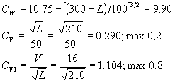
The combined sway/yaw acceleration is given by:
![]()
The heave acceleration is given by:
![]()
Roll motion and acceleration: {B400}
Roll angle is given by:
![]()
![]()
The period of roll is given by:
![]()
![]()
z = distance from the baseline to the roll axis of rotation
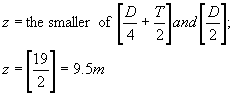
The tangential roll acceleration at the height, h above the baseline is given by:
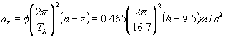
Pitch motion and acceleration: {B500}
Pitch angle is given by:
![]()
The period of pitch is given by:
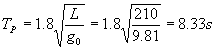
The tangential pitch acceleration at the length, l from the A.P. is given by:
![]()
Combined vertical acceleration: {B600}
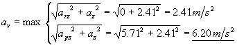
Combined transverse acceleration: {B700}
![]()
Since we want to have ary given as an angular acceleration and ay is small compared to the other terms, the transverse acceleration is calculated as:
![]() Forsat
Forsat
![]()
Combined longitudinal acceleration: {B800}
![]() Forsat
Forsat
![]()
Combination between acceleration in different directions
Vertical and transverse force: {C500}
Vertical force:
![]()
Transverse force:
![]() Forsat
Forsat
![]()
Vertical and longitudinal force:
Vertical force:
![]()
Longitudinal force:
![]()
Appendix 6 Calculation
of the Dynamic Gust Factor , Cdyn
According to "Snö och vindlast", Chapter 3:322
Ship design factors given from the ship designers:
Dynamic gust factor, Cdyn
Reynolds number
Ship design factors given from the ship designers:
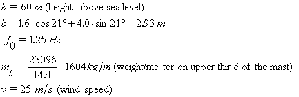
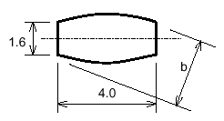
Figure A2.1, cross-section of the mast
Dynamic gust factor, Cdyn
| {eqv. (a)} | |||
{eqv. (b)} |
|||
{eqv. (c)} |
|||
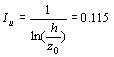 |
{eqv. (d)} |
||
{Ch. 2:32, table (a)} |
|||
{eqv. (e)} |
|||
{eqv. (f)} |
|||
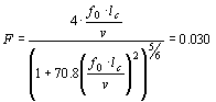 |
{eqv. (g)} |
||
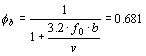 |
{eqv. (h)} |
||
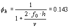 |
{eqv. (i)} |
||
{table a} |
|||
{eqv. (j)} |
|||
|
|||
{appendix A2:6, eqv. (b)} |
|||
![]() {(Ch. 3:51, eqv. (a)}
{(Ch. 3:51, eqv. (a)}
![]() 7
7
Appendix 7. Wind Pressure Calculations
The calculations leading up to the chosen design criteria regarding the pressure imposed by the wind on the sails is explained in some detail below.
Survival Condition
Using the top gust wind speed calculated above we got a total Bernouilli pressure of:
![]() [kN/m2]
[kN/m2]
Transferring to designers units we had:
![]() [kg/m2]
[kg/m2]
The above pressure was assumed to be applied as uniform load on the local panels in case of extreme wind conditions, and the mast standing at a right angle towards the wind. This must definitely be considered as an extreme case. See the note below. If the mast can survive wind speeds of 80.8 m/s folded together and turned against the wind this was considered sufficient.
Note
Using a Cl of 3.2 we could now calculate the wind speed in sailing when it is advisable to fold the mast together in order not to exceed the local pressure maximum of the sandwich panels. Assuming that 2/3 of the force was generated by "suction" on the leeward side of the flap we get:
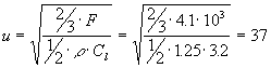 m/s
m/s
We now realised that using the survival criteria as design load for a sailing ship was very conservative. It was not reasonable to specify a sail that should withstand full storm without reefing. The resulting design would be far too heavy.
Full Sail Condition
Using the 3 sec. gust speed as design criteria, with a Cl of 3.2 (from the measurements described below) we got:
![]() [kN/m2]
[kN/m2]
Recalculating to designers units we had:
![]() [kg/m2]
[kg/m2]
But again we were designing the sails to withstand full storm conditions of 37 m/s wind speed. As mentioned above this would yield very heavy sails. The wing mast provides two mechanisms to prevent overloading of the panels. Designing for the average 10 min wind therefore seemed motivated. Any gusts above this limit would be taken care of by load relief from the mast.
As the design wind speed (25 m/s) is measured 10 m above the water surface it has to be corrected using a standard wind profile as the rig is positioned between 15 and 60 m above the surface. By averaging the wind speeds along the height of the mast we got a wind speed of 29.35 m/s. We had the wind speed variation with height z from DNV, see Ref. 16:
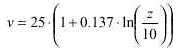 Equation 22
Using the heights 21.6, 32,3, 43.0 and 53.7 [m] we get:
![]() [kN/m2]
[kN/m2]
Recalculating to designers units we had:
![]() [kg/m2]
[kg/m2]
For comparison:
| The 10 min average speed of 25 m/s at a height of 10 m gave a pressure of 1250 N/m2, or 127 kg/m2. | |
| The 10 min average speed of 30.6 m/s at 45 m height gave a pressure of 1872 N/m2, or 191 kg/m2. |
As can be seen from above, due to the quadratic dependence of the pressure with the wind speed, it was important to choose the correct design wind speed. See also Figure 86.
---
Figure 86. The wind pressure dependence on wind speed
Appendix 8. Determination of Individual Forces on each Wing mast Member
For comparison the forces on each panel is determined from wind speed = 25 m/s. The wing mast profile can be found in Figure 87 below.
---
Figure 87. Profile plan with dimensions.
There is no information readily available on the Cl, Cd and CN for the separate profiles shown in Figure 87 above. This is not surprising since they were drawn by "freehand" at P-KEH. Moreover we cannot determine the individual profiles angle of attack a , nor their interaction. Since the measurements were not performed in such a manner that the individual profile’s coefficients could be determined, some "engineering judgement" had to be used to estimate these values. Some measurements of profiles with flaps folded out and other high lift devices can be found in [17]. From there the following general conclusions can be found:
| CNc/4 increases with increasing Cl. | |
| Typical value for "normal" asymmetrical profile at high a : Cl = 1.6, CNc/4 = - 0.05. | |
| Typical value at high a for a single flapped profiles: Cl = 2.8, CNc/4 = - 0.0875. | |
| Multiple flap profile at high a : Cl = 3.2, CNc/4 = - 0.1875. |
A square and linear fit of the above information yields, see Figure 88 below:
---
Figure 88. Square curve fit of the Cl-CN dependency. Linear approximation CN(Cl) = 0.0774-0.07332*Cl.
Looking at the profile plan in Figure 87 above we can estimate that the more curved the centreline of the profile, the more they will contribute to the lift, thereby having the largest rotating moments. It is therefore probable that the leading edge slat and the trailing flap will be induce larger force- and moment coefficients than the average values that were measured for the entire wing. The almost symmetrical mast profile will consequently contribute to a slightly lesser degree.
From Figure 88 we have that the square curve fit seems to decrease the CN with increasing lift at lower values of CL, this was judged unphysical and the curve was disregarded. The linear approximation was used to determine the individual profiles values of CN.
In order to determine the individual forces from each profile we have to make an assumption regarding the overall lift contribution from each profile. The calculations leading to the individual lift and moment distributions can be found in Table 31
Naming the first profile (the slat) no.1, the mast no.2 and the flap no.3 we have the following dimensions:
Profile no |
chord length c [m] |
quarter chord [m] |
profile depth [m] |
percent of chord [%] |
Area [m2] |
1 |
3.274 |
0.82 |
0.24 |
7.3 |
141.1 |
2 |
8.0 |
2.00 |
0.14 |
1.8 |
344.8 |
3 |
10.466 |
2.62 |
0.60 |
5.7 |
451.1 |
All, sum or average value |
Entire wing: 19.5 |
- |
- |
Average: 4.93 |
Sum: 937. Measurements: 838. |
Table 30. Dimensions for the individual profiles.
The discrepancy in areas between the summed areas and the area used during the measurements is due to the difference in projection.
From the measurements we have that the max. Cl was 3.2 for the entire wing. To calculate the forces acting on the individual profiles we first scale the lift coefficient linearly with the curvature of the individual profiles. To get the forces we then distribute the lifting force according to the area and lift coefficient ratios. For the area distribution the area value used in the measurements was used. The total lift, drag and yawing moment from the measurements at a wind speed of 25 m/s at an angle of attack a = 21° can be calculated to:
![]()
![]()
![]()
Since drag is dependent on the square of the lift force we can estimate the individual profile’s drag from the lift coefficient. The moment in each individual profile is also estimated using the approximate curve fit seen in Figure 88 above.
Table 31. Scaling the lift coefficient linearly with the depth of the profile : Look here please
Note on individual member forces estimation
The area based Cl of 3.27 is ok, using 838 m2 for the wing area. Area based Cd of 1.2 also seems ok. The lift (L) and drag (D) forces calculated in eqs.(x-y) above are judged coherent with the values here calculated for the individual profiles.
The values for CN are however considered slightly unrealistic. From ref.[17] it is clear that the pitching moment should be a function which is relatively independent of the angle of attack (a ). From DMI report (1) we see that this is not the case. Run 412 (the chosen configuration) has a pitch moment coefficient CN that varies 25% in a span of 0 - 20° . The extrapolation performed in Figure 88 above is also very rough. The changing CN with a in DMI report no. 1 indicates that there are some profile interaction effects that really needs to be looked into by CFD (computational fluid dynamics) or more detailed measurements before the individual profile’s pitching moments can be determined. In lack of such the values in Table 31 are used.
Appendix 9. Price and Weight Calculation for the Wing mast.
Table 32. Price and weight calculation for a25 m/s wing mast built in Denmark. : Look here please
Table 33. Price and weight estimate for a 20 m/s wing mast built in Denmark : Look here please
Table 34. Price and weight estimate for a 20 m/s wing mast built in a low-price country. : Look here please
Appendix 10. Fuel Consumption on the Atlantic and Indian-Pacific Trade Patterns
Figure 89. Fuel consumption on the Atlantic trade pattern
Figure 90. Fuel consumption on the Indian-Pacific trade pattern
Appendix 11. Polar diagrams from DMI/SL.Reproduced from Ref. 7.
Figure 91. Speed for given thrust and 10 m/s wind
Look here please
Figure 92. Thrust for given speed and 10 m/s wind.
Look here please
Figure 93. Rudder angle for heading to true wind, 10 m/s.
Look here please
Figure 94. Drift angle for given heaading to true wind, 10 m/s of wind.
Look here please
|
[Front page] [Top] |