Guidelines on remediation of contaminated sites
Appendix
5.2
Convection model for gas invasion into surrounding buildings
This Appendix describes a model for landfill-gas transport into buildings placed outside of landfill area producing gas. The model, which calculates the convection contribution, is based on a worst-case scenario, where the entire quantity of gas being transported enters the building /1/. As such, this convection model is simpler than the model for convection contribution which is described in Appendix 5.3.
Calculation assumptions and formulae
A landfill with soil gas concentration Cp is situated at a distance x from a building, as shown in Figure 1. Gas transport is assumed to take place solely in the upper unsaturated zone. The landfill has a positive pressure Ps in relation to pressure at the building. Atmospheric pressure is Patm.
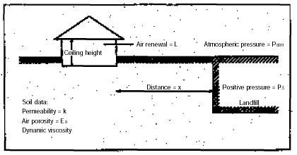
Figure 1
Diagrammatic presentation of model for transport of landfill gas to surrounding
buildings.
In this model, the extent of the landfill is assumed to be much greater than the distance to the building. The following applies to the situation of equilibrium:
| (1) |
where:
| a | = | the ratio between inside-air concentration of the building and soil gas concentration of the landfill |
| k | = | air permeability (m2) |
| Ps | = | landfill positive pressure (Pa) |
| m | = | dynamic viscosity (kg/m ž s) |
| x | = | distance (m) |
| l | = | ceiling height (m) |
| L | = | air renewal (s-1) |
The period elapsing before establishment of pressure gradient tssp (Equation 2) and equilibrium concentration tssc (Equation 3) is given by
| (2) | |
| (3) |
where: Ea = air porosity (unitless)
Patm = atmospheric pressure (Pa)
Data basis
The calculation formulae (equations 1-3) state the necessary data. Empirical data for input data are listed in Table 1. For constructional data, see Table 1 in Appendix 5.3.
Table 1
Empirical data for transport model data.
Air permeability, k |
m2 |
||||||||
|
10-13 10-12 2 ž 10-11 |
||||||||
Positive pressure in the site, Ps |
Pa |
||||||||
|
0 – 2,000 |
||||||||
Dynamic viscosity, m |
kg/m× s |
||||||||
|
1.8 ž 10-5 1.1 ž 10-5 1.5 ž 10-5 |
||||||||
Air porosity, Ea |
unitless |
||||||||
|
0.1 0.1 0.1 0.3 |
1)
Estimated value. See also Table 2 and 3 in Appendix 5.8.References
Little, J.C., Daisey, J.M. and Nazaroff,
W.W: Transport of Subsurface Contaminants into Buildings. An Exposure Pathway for
Volatile Organics. Environmental Science and Technology. Vol. 26. No. 11, 1992, p.
2,058 – 2,066. |