VOC Emissions from Manufacturing Processes
Appendix A
Appendix A: Photos (Catalogue of measures)
Dissolver and reactor
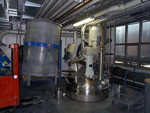
Photo 1:
Dosing of liquid raw material into a Dissolver, condensation system and flexible hose
system on the dissolver lid.

Photo 2:
Dosing station for mobile bins with exhaust air extraction and curtain.
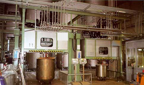
Photo 3:
Dosing station for mobile bins (semi-closed).
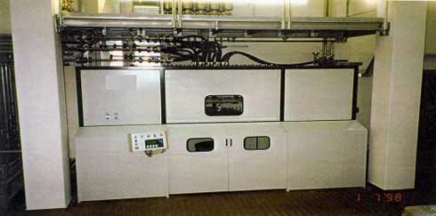
Photo 4:
Dosing station for mobile bins, full encapsulated.
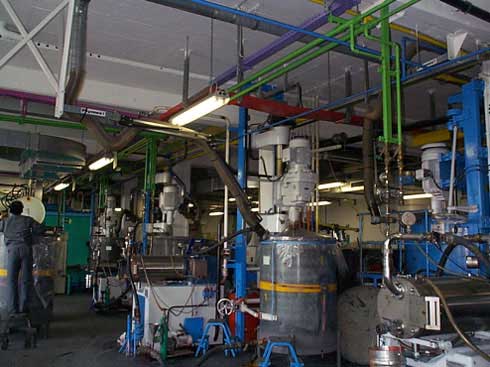
Photo 5:
Dissolver with mobile bin and exhaust air extraction by flexible hose during dosing of
liquids and dispersing.
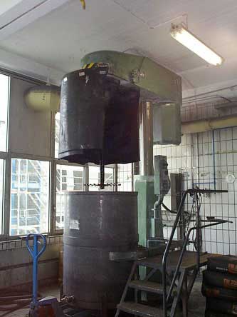
Photo 6:
Encapsulation of dissolver with mobile bin and exhaust air extraction.
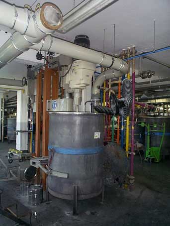
Photo 7:
Dissolver with mobile bin and flexible hose with extraction hood.
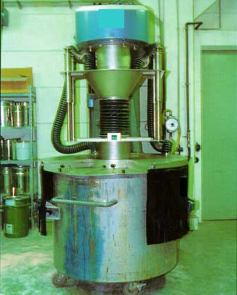
Photo 8:
Encapsulation of dissolver.
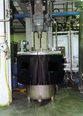
Photo 9:
Encapsulation of dissolver.
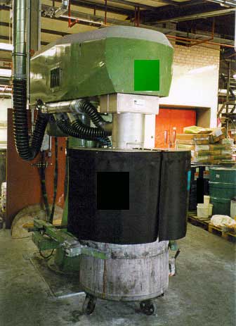
Photo 10:
Encapsulation of dissolver.
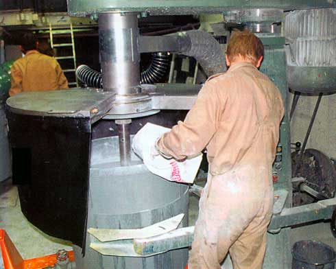
Photo 11:
Dissolver encapsulation with possibilities for manual addition of powder.
Photo 12:
Dissolver with dosing lid.
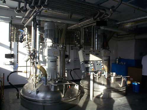
Photo 13:
Closed dissolver system with automatic liquid dosing via pipe and condensation system.
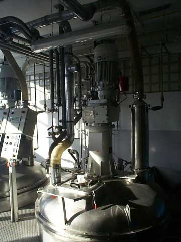
Photo 14:
Closed Dissolver system with automatic liquid dosing via pipe, condensation system and
dust extraction system by flexible hose.
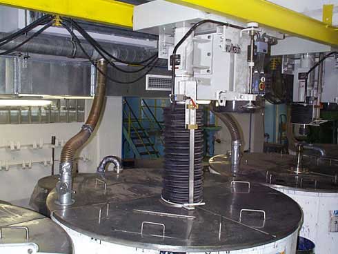
Photo 15:
Finish tanks with exhaust air extraction via flexible hose and concertina expansion
joint at the agitator shaft.
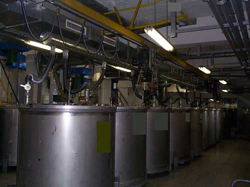
Photo 16:
Finish tanks with exhaust air extraction via flexible hose and exhaust air piping
system and above the ventilation system for the working environment.
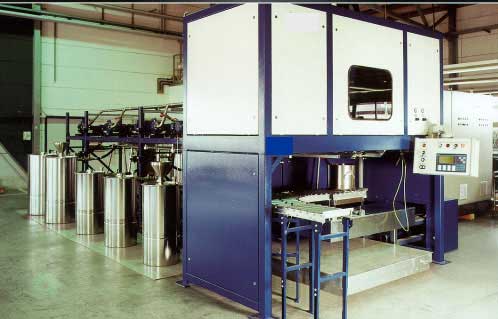
Photo 17:
Automatic filling station.
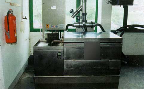
Photo 18:
Rinsing basin with automatic, directed exhaust air flow.