Autonomous weeders for Christmas tree plantations - a feasibility study
Bilag
A
A specification of behavioural requirements for an autonomous tractor
Simon Blackmore, Henrik Have and Spyrus Fountas
The Royal Veterinary and Agricultural University,
Section for AgroTechnology
1.1 Abstract
Over the last decade new information technologies, such as GPS and GIS, have been introduced that has allowed the scale of management to be reduced from farm level, down to field level and occasionally to sub field level. With the advent of new information technologies, such as behaviour-based robotics, this process can be continued into the future by looking at an even smaller scale such as plant scale technology or Phytotechnology. (From the Greek phyto, which means plant) These new Phytotechnology units will be small autonomous systems that can behave in a sensible manner for long periods unattended, caring for the individual plant from seeding through to selective harvesting. With this level of sophisticated equipment, it is likely that higher value crops such as in horticulture or forestry will be able to justify such an investment first. Very little new hardware is needed but the challenge is in defining and implementing sensible behaviour and developing the systems architecture to support it. This paper sets out the criteria for the design of such a system.
1.2 Introduction
To further improve the efficiency of developed agriculture, horticulture and forestry found in northern Europe a new concept is being developed that has identified that multiple small autonomous machines would be more efficient than traditional large tractors. In order to meet this hypothesis a small tractor with intelligent control is proposed. These vehicles will be able to work longer hours at a slower rate, giving the same, or even greater, overall output as conventional systems. Each vehicle would be capable of working 24 hours a day all year round, in most weather conditions and have the intelligence embedded within it to behave sensibly in a semi-natural environment such as horticulture, agriculture, parks and forestry, whilst carrying out a useful task. Moreover, it may have less environmental impact if it can replace the over-application of chemicals and the high usage of energy, such as diesel and fertiliser, by control that is more intelligent. Additionally, it will require smaller incremental investment and will have lower labour costs. Finally, it may have very low soil compaction that would lead to a more sustainable production system.
Agriculture, horticulture and forestry has benefited in the past from a succession of technological developments that have brought greater productivity and economic efficiency to systems operated in many regions of the globe. Historically, the emphasis of these developments has been on the mechanisation of field operations to increase work rates achievable by individual operators. Today, however, the general trend of increased efficiency through the use of larger, more powerful, machines may be superseded by the adoption of newer information based technologies that may ultimately enable reliable autonomous field operations to be viable (Earl et.al. 2000). A review of possible platforms was carried out by Ellenreider (1996) and a review of automatic steered tractors is given in Wilson 2000.
This scale-reduction process, started by Precision Farming, may lead to the possibility of individual plant care systems called Phytotechnology. (Shibusawa 1996) Precision Farming is a set of methodologies that utilise technologies such as the Global Positioning System (GPS), Geographical Information Systems (GIS) and Management Information Systems (MIS) as well as the sensors and controllers in the field, to reduce the area of management from the whole farm down to field level and on occasions sub field level. Due to the increased data processing required to cover a complete field at the individual plant level, only certain operations are carried out with human intervention these processes lend themselves to different forms of automation, especially in high value crops. Two good examples of this process are mechanical weeding and field scouting.
1.3 Mechanical weeding
As most horticultural crops are grown in widely spaced rows, inter-row mechanical weeding (weeding between the rows) has been popular since mechanisation started. The only problem has been in assessing the relative distance between the crop and the weeding tool, as nowadays it is difficult to keep the tractor exactly parallel with the crop row. To overcome this problem, another operator is used to steer the weeding tool relative to the crop row, but this increases the cost. Recent developments have lead to the use of machine vision to recognise the contextual information of the crop rows and steer the tool to within a few centimetres of the plants. This idea was first tested in 1992 (Hoffman 1992, Steinhauser 1994) and has more recently been commercialised by the Danish Institute of Agricultural Sciences and Eco-Dan (Søgaard, 2000).
Intra-row weeding (weeding within the row) has proved to be more difficult due to the problems of discriminating between crop plants and weed plants. A number of techniques have been tried notably categorising plants due to their spectral reflectance characteristics. (Bennedsen 2001) These techniques have worked well in controlled environments, such as the laboratory, but traditionally have not proved so reliable in natural lighting.
An alternative development has been to uniquely identify each individual crop plant by recording the position of each seed as it was planted. (Ehsani 2000) This is not as difficult as it sounds, as technology has developed sufficiently in the form of now standard high-speed PCs and the Real-Time Kinematic Global Positioning System (RTK GPS). Most desktop PCs can easily manage the data rates required during planting as they can also store the 100,000 seed positions in each hectare for Sugar Beet or 10,000 Christmas trees per hectare. The RTK GPS can resolve positions down to 1 cm in stationary mode and 2 cm whilst moving slowly. As the plant positions are now known, a mechanical intra-row weeder can be controlled to move around each plant. Whether this level of accuracy can be maintained in agricultural conditions remains to be seen but a 2 cm systemic shift would result in all the crop plants being removed! (NB Denmark is moving 1 cm to the East each year).
1.4 Field scouting
There are many sensing techniques that that can ascertain crop and soil health. Many of them could be used now in production horticulture, apart from the fact that they take a long time to process the data. Examples are multi-spectral response from the plant canopy that can indicate stress (whatever the cause) and chlorophyll content is associated with crop vigour. Carbon dioxide (CO2) has been associated with soil health, Ethylene can be associated with pest attack and conductivity has been correlated with soil moisture. (Waine 1999, Waine, et.al. 2000) Soil nitrates, organic matter, Charged-ion Exchange Capacity (CEC), pH and soil moisture have been measured at different depths using Near Infra-Red (NIR) reflectance with a soil photo spectrometer. (Shibusawa 2000) Ion Selective Field Effect Transistors (ISFETs) can be modified to be sensitive to nitrates, pH and other factors from soil solution. (Birrell #) Most of these sensing systems are still in the research phase but they hold great promise to improve our understanding and management of the growing crop and its environment. If these systems were mounted on an autonomous vehicle then they could be used commercially now and not have the associated problems of paying an operator to wait in the field while the processing takes place.
1.5 Autonomous vehicle requirements
Both of these tasks (as well as many more) could be mounted on a small autonomous vehicle that could roam the field carrying out its task over prolonged periods of time but to be able to achieve this the vehicle must have certain attributes and behaviours.
The main design parameters for this proposed vehicle are that it is:
| Small in size (and therefore unmanned) | |
| Light weight | |
| Exhibit long-term sensible behaviour | |
| Capable of receiving instructions and communicating information | |
| Capable of being co-ordinated with other machines | |
| Capable of working collaboratively with other machines | |
| Behave in a safe manner, even when partial system failures occur | |
| Carry out a range of useful tasks |
1.5.1 Small size
A small vehicle size is very meaningful as it ensures higher precision of operation, lower incremental investment and is relatively safe during system failures. The vehicles will probably be 1-2 metres long and in the 10-30 hp range, as they will require an internal combustion engine. An engine is needed due to the energy - density requirement that battery power alone cannot supply. Smaller vehicles of less than a metre and around five hp could be developed for highly specialised tasks with low energy requirements such as non-contact sensing. Much smaller systems could be developed when higher density energy sources become available such as fuel cells. The control systems described here could be applied to any size platform. Incremental investment and replacement of the vehicle and high production runs can be achieved by possibly using standard car components. The farmer’s and the public’s acceptance will be increased with the launch of small autonomous vehicles rather than bigger ones. These vehicles will have the advantage to be more site-specific than larger machines, due to higher manoeuvrability. Inevitably, the smaller vehicle will have a lower work-rate but as it will be unmanned, it can work for longer hours to compensate. Using site-specific fertilising and spraying, it can achieve a further reduction in inputs, if combined with appropriate sensors These small machines will be able to do selective and more precise treatments and can potentially be developed to sense and care for individual plants or sub plant manipulation, e.g. thinning, pruning, selective harvesting etc.
1.5.2 Light weight
The lightweight design parameter is important as it implies reduced soil compaction. Chamen (1994) has identified that a 70% energy saving can be made in cultivation energy by moving from traditional trafficked systems (255 MJ/ha) to a non-trafficked system (79 MJ/ha). This was for shallow ploughing and did not include any deep loosening. From this we estimate that 80-90% of the energy going into traditional cultivation is there to repair the damage done by large tractors. If we can accept the premise of a light intelligent vehicle replacing the large tractors, there is the possibility to develop a completely new agricultural mechanisation system. As we have the possibility of very low compaction and mechanical weeding, then we do not need to plough, but use micro-tillage and direct drilling, which could play a major role in conservation agriculture. As the natural healthy soil bio-system modifies the soil structure into a near ideal situation for root development, almost zero compaction agriculture could be developed that allows the natural processes to enhance production rather than introducing energy to compact and then recreate a good soil structure. As the vehicle is inherently light, it should also require lower energy inputs although this is offset by the higher efficiencies of the larger engines.
1.5.3 Autonomous behaviour
The main behavioural requirement of this vehicle is that it will have sensible long-term unattended behaviour in a semi-natural environment such as horticulture, agriculture, parkland and forestry. This sensible long-term behaviour is made up of a number of parts. Firstly, sensible behaviour needs to be defined, which at the moment is device independent. Alan Turing defined a simple test (the Turing test) for artificial intelligence, which is, in essence, if a machine’s behaviour is indistinguishable from a person then it must be intelligent. We cannot yet develop an intelligent machine but we can make it more intelligent than it is today by defining a set of behaviour modes that make it react in a sensible way, defined by people, to a predefined set of stimuli in the form of an expert system. Secondly, it must be able to carry out its task over prolonged periods, unattended. When it needs to refuel or re supply logistics, it must be capable of returning to base and restocking. Thirdly, safety behaviours are important at a number of levels. The operational modes of the machine must make it safe to others as well as itself, but it must be capable of graceful degradation when sub-systems malfunction. Catastrophic failure must be avoided, so multiple levels of system redundancy must be designed into the vehicle. Fourthly, as the vehicle is interacting with the complex semi-natural environment it must use sophisticated sensing and control systems, probably in an object oriented manner, to be able to behave correctly in complex situations.
Behaviour in general terms is a thematic set of reactions to a stimulus. Behaviour-based systems provide a means for the vehicle to execute a behaviour e.g. navigation, by endowing the vehicle with behaviours that deal with specific goals independently and coordinating them in a purposeful way (Arkin 1998). Four main behaviour modes for this vehicle have been identified.
1.5.3.1 Navigation mode
The vehicle must be able to navigate safely to a desired position. We estimate that the vehicle will be in navigation mode around 80-90% of its time, as positioning itself and its working tool is the vehicle’s main requirement. The vehicle must be able to plan an efficient route to the target point taking into account known objects, tracks, paths, gateways etc., as well as being able to react to unknown objects or situations. This high-level behavioural mode subsumes other lower level behaviours such as route planning and object avoidance.
Deterministic planning of the optimal route for the vehicle between the current position and the desired position requires detailed information about the physical terrain and attributes. This type of spatially related data is best stored and processed in a geographical information system (GIS). Route planning software is currently available but it must take into account the characteristics of the vehicle, such as width, height, turning circle etc., as well as expected time of arrival so that speeds can be calculated. The goal for the vehicle should be to arrive at a predetermined position, attitude and time.
When objects are detected, a sub system will track the range and bearing of the nearest objects until it is clear that the object may become an obstacle, the vehicle will slow its speed to a safe distance and then stop. If the object does not move then the vehicle will perceive it as stationary and give an audible warning to an animal or human to move out of the way. If the obstacle remains stationary then the vehicle will go around it and record the size and position in the GIS. On the other hand, if the object moves, it will then wait for it to move out of the way and then proceed. If finally the object approaches the vehicle, it will perceive the object as threat, and it will close down into a safe mode.
A specialised navigation mode is refuelling. When the vehicle needs to refuel, restock logistical requirements (e.g. replenish chemicals or replace worn tines) or need other attention, it must navigate back to its base and connect with the docking station. Once refuelled and restocked or manually repaired, it can then go back to the field and continue.
1.5.3.2 Exploratory mode
The vehicle will be fitted with local environment sensing systems, which will enable it to explore and record an unknown environment. If the vehicle is initialised in an unknown area with an empty GIS, it can start to populate the GIS with its own data. In the exploratory mode, the vehicle will record data from all its sensors at the current position. If it assesses that it is safe to move ahead it will then move slowly recording relevant data as it moves. Depending on the search pattern required (zigzag across an area, follow boundaries etc.) it could work out a route dependant on conditions. Once an area has been explored and surveyed, more optimal deterministic route plans can be made to carry out surveys. A good example would be a self-adaptive soil survey based on the position and the results from the sensor. Fewer readings could be taken from seemingly homogenous areas, while more intensive sampling can occur in areas of heterogeneity.
1.5.3.3 Self-awareness mode
The vehicle will also be fitted with self-sensing systems built into it to keep a check that all the major parameters are within normal limits. Some of these parameters will be fuel level, engine temperature, tilt angle and outside temperature. (It may be beneficial to add a small weather station as well so that it can return to base or close down if conditions get too bad.) If any of these parameters go outside expected limits, it can give non-critical warnings but if they are seen as critical then the vehicle can move into one of its safe modes. This behavioural mode is not mutually exclusive to any of the other modes so may be run entirely in parallel as a separate process.
1.5.3.4 Implement task mode
The vehicle will have mechanical, electrical power and communication interfaces to allow a range of implements to be fitted so that the vehicle and implement can undertake specific tasks such as mechanical weeding or crop sensing. The mechanical interface is likely to consist primarily of a category zero three-point linkage, which is a recognized standard coupling. Alternative arrangements may be considered if a tighter mechanical coupling is required. The power and the communication interface may well utilize another existing standard such as the control area network (CAN) bus or LBS connector. In this model, we are taking the same roles as existing tractors and implements but scaling them down. The vehicle, like the tractor, will supply the motive power and positioning for the more specialist implement. Common data like positioning, attitude etc. is more closely linked with the vehicle as it is likely to be common to all implement tasks. The data will be available to the implement via the bus. Each implement will have at least one job computer to control the implement tasks and send requests to move to the vehicle. Whilst the implement task is active, the implement controller will control the actions of the vehicle. The implement will have at least one ‘focus area’. That is, the active area on the vehicle such as the view from the camera or weeding area of the tine. This must be matched up to the ‘target area’ by moving the vehicle or the implement may have an extra degree of freedom. In either case, when the implement has finished in one area, it will instruct the vehicle to move to the next area. If a continuous process can be achieved then the vehicle could move along a predefined path and speed while the implement works independently.
Each implement will have its own special requirements for calibration and error checking. It is envisaged that each implement task will have sub-behaviours and that all the processes can be properly calibrated or checked. This will allow the task to periodically carry out a self-check to ensure all functions are working correctly. If an implement task recognises that the weeding tines are worn or that the camera lens is obscured it can carry out remedial action or return to base for servicing.
1.5.4 Communication
Communication between the various processes within the vehicle will be implemented by using a bus system and processor nodes. The bus will be a recognised standard such as CAN or Ethernet but the communication traffic will be kept to a minimum by utilising a high level message passing protocol. All messages will be in text form and a log file will be kept for faultfinding and error checking. All processes will be closely coupled to their respective sensors and actuators directly to avoid any closed loop control systems being adversely affected by time lag over the network. Each vehicle will have a supervisor process (probably in the form of a laptop) that will display the status, keep the log file, and check that the messages are within bounds for a second level of safety.
Communication between a vehicle and the coordinator will be through the vehicle supervisor and a radio Ethernet LAN or other wide bandwidth protocol. Peer-to-peer communication between the vehicles will be implemented in the same way.
1.5.5 Co-ordination
A computer at the farm office, operated by the manager, will hold the overall control of the autonomous vehicles. It should have an independent real time real-time video link to each vehicle with a steerable camera so that the manager can get a quick impression of what the vehicles are doing. This can be combined with a mimic status display of all the functional parameters of the vehicles.
When a new job is planned or a new vehicle is added to the team, an optimisation routine can be invoked to calculate the best strategies, initial routes, placements etc. for the vehicles. This overall plan can then be decomposed into specific tasks for each vehicle and send via a dedicated radio link. The coordinating PC will also hold the master GIS that can be synchronised with the vehicle GIS at the end of each day. The coordinator will also prepare all the required operational and application maps as well as the actual treatments carried out by the vehicles. Other functions will keep records of the logistics.
At times it may be more convenient to have a mobile base station, in the form of a trailer, within a distant field that can serve as a remote docking station for logistics, contain the differential GPS base station, radio repeater, weather station etc. It should have the capacity to allow multiple machines to self dock on the trailer after work to allow the operator to then hook it up to a car or tractor and move the whole system back to the farm for servicing or storage.
1.5.6 Collaboration
As part of the overall design philosophy, these small vehicles must be capable of collaborating on mutual tasks. This will help to improve the works rates and allow the time critical tasks to meet their deadlines by scaling up the number of operational machines. As each machine will still be independent and autonomous, its tasks will be coordinated centrally with the other vehicles to achieve optimal effectiveness. High levels of system integration later may allow the vehicles to work as one entity.
1.5.7 Safety
The autonomous vehicles should always operate in a safe state. Safety is expressed in terms of safety to others, safety of self and safety of the crop. These safety issues are addressed in terms of intelligent sensing and redundant systems. Intelligent sensing involves more than one transducer sensing the same object. Multiple transducers can sense the same measurements for double-checking and contain redundant data to improve reliability. The embedded processor arbitrates between the transducers outputs and chooses the better one. (Blackmore and Steinhauser, 1993) An example of this approach is by using ultrasonic range sensors combined with a laser scanner to track potential obstacles in front of the vehicle.
Redundant systems allow the capability of graceful degradation during partial system failure. Graceful degradation is the process where parts of the system fail but the overall system is capable of functioning even though with a reduced capability. This generally involves only part of the task being fulfilled, which is arguably better than a complete shut down. Functionality is gradually reduced as faults increase. Only systems with redundant sub systems can allow this type of behaviour.
The primary safety modes for the vehicle and implement task will be
- In a safe operation
- All vehicle and implement systems are operating within normal parameters
- Safe operation with warnings
- Operating safely, but there are some warnings about abnormalities (e.g. low fuel)
- Partial system shut down – mobile
- Partially shut down, although it remains mobile (e.g. camera lens obscured)
- Partial system shut down – immobile
- Partially shut down, the vehicle is immobile (e.g. transmission fault)
- Stopped – still communicating
- Fully shut down, but it still communicates with the co-ordinator (e.g. internal fault)
- Dead
- The system has fully shut down and there is no communication with the co-ordinator
To ensure that a controlled process is reliable, always available and safe, it is necessary to perform condition monitoring, predictive maintenance and fault diagnosis, as well as ensuring the quality of the system components (the sensors, the actuators, the process control computers, etc.). One of the main goals is an early diagnosis (detection, isolation and identification) of faults, whilst they are incipient and hard to detect and isolate. Another goal is to ensure that the process can tolerate faults through control system reconfiguration or by a graceful degradation of safe and stable closed-loop performance. Human factors and man-machine interfaces are the final links in the safe operation of technical processes so full data about the vehicle and task should be available in an understandable form.
Blanke et.al. (2001) refer to fault-tolerant control systems that employ redundancy in an automation system to make "intelligent" software that monitors behaviour of components and function blocks. Faults are isolated and appropriate remedial actions taken to prevent that faults develop into critical failures. The overall fault-tolerant control strategy is to keep the automation system’s availability and accept reduced performance when critical faults occur.
Control of the vehicle will also be layered. Full automation will occur when the vehicle system has complete autonomy in its own actions after the task has been defined. At the other extreme, an operator can control the vehicle’s main control functions. This can be achieved by either using a joystick, or more directly, adjusting each control parameter individually from either the supervisor laptop or the coordinator PC via the radio Ethernet.
As these vehicles are being designed to work for long periods unattended, there is a significant likelihood of theft. If someone approaches the vehicle, it will shut down into a safe mode until the person goes away. A legitimate operator could have access to the vehicle control by using a radio key fob but without it, the machine could go into stasis recording activity and sending this record with its position back the coordinating PC. If the vehicle was seen to move without powering the drive motors, then an alarm could be triggered.
1.6 Vehicle concepts
Although this paper is predominantly focussed on the specification of requirements independent of the hardware, it is useful to consider alternative platforms.
We are considering using three main types of vehicle layout:
- Conventional small tractor (e.g. 26 hp Hakotrac 3000)
- Specialised portal tractor (small and medium sized)
- Highly specialized very small vehicle
1.6.1 Conventional small tractor
This type of vehicle has many advantages in that it is commercially produced, reliable, multi-purpose product supported by the manufacturer. All the mechanical and hydraulic systems conform to recognised standards. The autonomous systems can be retro fitted and the human control interfaces would be modified to include actuators.
Although the vehicle is lighter than most conventional tractors, (see figure 1) it is still heavy enough to cause soil compaction. Another difficulty is to fit the shear bulk of the autonomous systems, as the original tractor design does not allow for this type of addition. Furthermore, as the tractor is of conventional design, (2 rear wheel drive, 2 front wheel drive and steer) it has limited manoeuvrability.
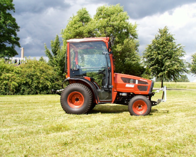
Figure 1.
The Hakotrak 3000. This tractor is currently being adapted to accept the
Agronav automatic steering system from GEO-TEC as part of a collaborative Danish research
programme called Autonomous Platform and Information system (API).
Table 1.
The technical requirements for the small conventional tractor
Power |
20 - 30 hp |
Engine |
Diesel |
Speeds |
Infinitely variable within 3 ranges, hydrostatic |
Controls |
Mechanically operated hydrostatic |
Wheels |
Four wheel drive |
Chassis |
Medium ground clearance |
Implement mounting |
Front three-point linkage |
1.6.2 Portal tractor
The small portal tractor will have to be completely fabricated as no known commercial examples exist. It will be highly manoeuvrable as it will be 4-wheel drive and 4-wheel steer, which will greatly help the control algorithms when accurate positioning is required. It should be capable of carry a range of implements that will be centre mounted within the portal frame of the tractor, such as the mechanical weeding tool. A good example of such a vehicle was designed and built by two Master of Science students (Madsen and Jakobsen) at the Danish Technical University in 2001 and is shown in figure 2.
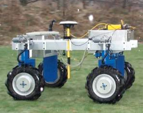
Figure 2.
Small portal tractor from the Danish Technical University
The larger portal tractors are produced in great numbers in Japan, for working in paddy fields. They have the advantage of being designed and built for the agricultural environment, light weight, high ground clearance and has standard category zero (or one) rear three-point linkage. The example in Figure 3 has 4WD, 2WS but a 4WS could be easily made by using two front axles.
Table 2.
The technical requirements for the smaller portal tractor
Power |
10 – 15 hp |
Engine |
Internal combustion engine (Battery at the moment) |
Speeds |
Infinitely variable wheel motors |
Controls |
Electronic interface |
Wheels |
Four wheel drive (4WD) |
Chassis |
High ground clearance |
Implements |
Centre mounted |
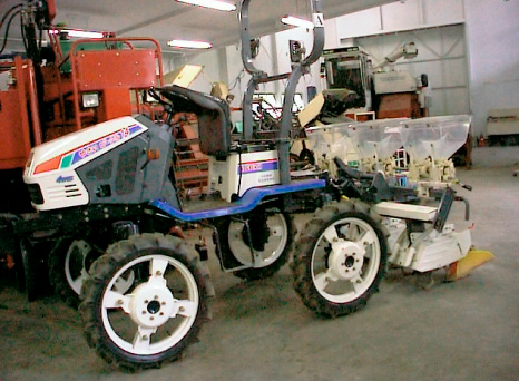
Figure 3.
A Japanese, larger type, portal tractor.
Table 3.
The technical requirements for the larger portal type tractor
Power |
10 – 20 hp |
Engine |
Diesel |
Speeds |
Conventionally geared |
Controls |
Mechanical |
Wheels |
Four wheel drive |
Chassis |
High ground clearance |
Implement mounting |
Rear three-point linkage |
1.6.3 Very small vehicle. (The ‘Beetle’)
This type of vehicle is probably as small as an agricultural vehicle can get (~1m), as it needs to carry enough energy for the required tasks as well as being able to remain mobile over cultivated soil and crop residues. Each type of vehicle will be highly specialised and contain an integrated tool such as a grass cutter (figure 4). To achieve such a small size, very high levels of integration will be needed.
Figure 4.
Simple schematic drawing of the beetle
Existing grass cutting equipment could be modified to give the required mobility and carry the associated control equipment. This could cause problems due to the bulk of the current equipment. This vehicle is currently being evaluated for suitability of autonomous Christmas tree weeding by the authors.
Table 4.
The technical requirements for the beetle
Power |
~ 5 hp |
Engine |
Petrol |
Speeds |
Fixed speeds |
Controls |
Electro-mechanical |
Wheels |
Four wheel drive |
Chassis |
Very low clearance (dependant on task) |
Implement mounting |
Integral grass cutter |
1.7 Conclusions
This paper has defined a set of requirements that form the basis for a control system that should be capable of behaving sensibly in a semi-natural environment. Behaviours modes have been described as well as the philosophical approaches to the final design from a top-down approach. Graceful degradation through using redundant systems has been identified as a key element in the production of a safe autonomous vehicle. Some alternative vehicle platforms have been considered.