Pesticides Research No. 116 2008 of fungicide application in winter wheat
3 Results
- 3.1 Characterisation of the sites
- 3.2 Yields
- 3.3 Diseases
- 3.4 Sensor measurements of crop parameters
- 3.5 Fungicide deposition
- 3.6 Fungicide deposition at different driving speed
3.1 Characterisation of the sites
The soils at the experimental sites were characterised by measurements with RTK-GPS, EM38 and MobilTDR during spring of 2005 and 2006.
The elevation at the corners of each plot was measured using the RTK-GPS, and this was used to derive mean elevation, mean slope and mean aspect for each plot. The elevation at the Nissumgård site in 2005 varied 10 m across the field with a depression at the centre of the field (Fig. 1). At Schackenborg the field sloped towards northwest with a 6 m difference in elevation across the field (Fig. 2). There were little elevation differences for the Nissumgård site in 2006 (Fig. 3), whereas there was a small depression in the north-eastern part of the experimental area at Dybvad (Fig. 4).

Figure 1. Mean elevation at Nissumgård in 2005.
The soil electrical conductance in two depth intervals (based on measurement with the EM38 sensor in vertical and horizontal position) were measured and interpolated to derive the mean conductance for each plot. The electrical conductance largely reflects the variation in soil texture with low conductance corresponding to sandy soil. There was a large variation in electrical conductance at the Nissumgård site in 2005 (Fig. 5), which only partly corresponds to the topography (compare Figs. 1 and 5). The electrical conductance at Schackenborg showed a large area with sandy soil in the centre of the field, and an area of clayey soil towards the north of the field (Fig. 6). The Nissumgård site in 2006 varied from sandy soil at the southern end to sandy loam at the north-western end (Fig. 7). A similar variation from west to east was seen at Dybvad (Fig. 7) with high electrical conductivity in the depression.

Figure 2. Mean elevation at Schackenborg in 2005.
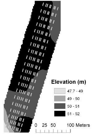
Figure 3. Mean elevation at Nissumgård in 2006.
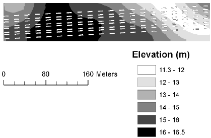
Figure 4. Mean elevation at Dybvad in 2006.
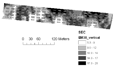
Figure 5. Soil electrical conductance measured with EM38 using vertical polarisation at Nissumgård in 2005.
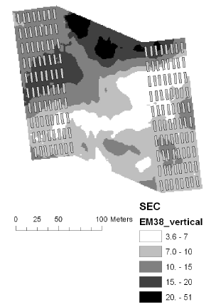
Figure 6. Soil electrical conductance measured with EM38 using vertical polarisation at Schackenborg in 2005.
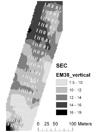
Figure 7. Soil electrical conductance measured with EM38 using vertical polarisation at Nissumgård in 2006.
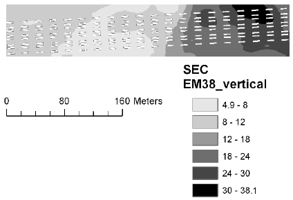
Figure 8. Soil electrical conductance measured with EM38 using vertical polarisation at Dybvad in 2006.
The soil water content was measured with TDR in early April 2005 and early May 2006 and reflects the soil water holding capacity to 50 cm depth. These measurements were interpolated for each plot. The soil water content correlated with the EM38 measurements, although there were separate relationships at the four sites and there was some disparity in the relationship at Schackenborg (Fig. 9ab). There was an even closer relationship between impedance measured using the TDR sensor and conductance measured using EM38 (Fig. 9cd).
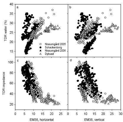
Figure 9. Relationship between TDR measurements of soil water capacity and impedance to 50 cm depth and EM38 measurements of conductance measured using either horizontal or vertical polarisation.
Soil samples were taken at 10 positions at each site for characterisation of soil texture. These positions were chosen based on the TDR and EM38 map to maximise the variation in soil conditions. A comparison of the soil texture measurements and the TDR and EM38 measurements is shown in Fig. 10, where soil clay and soil organic matter contents have been chosen as indicators of soil texture. There is close relationship between soil clay content and soil water content measured using TDR (Fig 10a). However, the measurements of soil water content at Dybvad appears to be lower than for the other sites, which may be related to the fact that these measurements were taken on 9 May and some evapotranspiration may have reduced soil water content at this point in time. There was also a close relationship between soil clay content and EM38 measurements at most sites (Fig. 10c). However, the scatter was much larger at Schackenborg due to the large variation soil organic matter content at this site (Fig. 10d).

Figure 10. Soil water content at field capacity (TDR) and soil electrical conductivity (EM38) related to soil clay content and soil organic matter in the top soil.
All plots in 2005 were assessed for presence of weeds and for homogeneity of the plant cover on 12 May 2005 at Nissumgård and 11 May 2005 at Schackenborg. The most inhomogeneous plots at Nissumgård occurred in the low area with the highest soil electrical conductance (Fig. 11a). The weed cover was particularly large and rather uniform at Schackenborg (Fig. 11d), and the weed flora here was dominated by Poa annua. The weeds occurred patchier at Nissumgård and the weed flora was also more diverse here.

Figure 11. Homogeneity of the crop stand and weed cover of the plots in May 2005 depending on soil electrical conductance measured with EM38 using vertical polarisation at Nissumgård and Schackenborg.
The experiments in 2006 were also assessed for weeds and homogeneity. The site at Nissumgård had several plots with poor establishment and winter damage due to molehills. There were a few plots at Dybvad with a substantial population of grass weeds.
3.2 Yields
The average dry matter yields at Nissumgård and Schackenborg in 2005 were 5.71 and 5.78 t ha-1, respectively. The average dry matter yields at Nissumgård and Dybvad in 2006 were 6.19 and 7.29 t ha-1, respectively. An ANOVA model including the two treatments, their interactions and block showed considerable variation between experimental sites in the variation explained by the model and in the C.V. (Table 4). The C.V. was particularly high at Nissumgård in 2006. However, a comparison with other sensor measurements did not indicate that any of these should be discarded due to errors in yield determination. The large variation at Nissumgård in 2006 may therefore be attributed to variation in crop establishment.
Table 4. Results of ANOVA for grain dry matter yield, either uncorrected or adjusted for fungicide costs (net yield). The R² of the model, the significance levels of the experimental treatments and the coefficient of variation (C.V.) are shown. The net yield was calculated by subtracting fungicide costs (373 DKK L-1 Opus) and application costs (65 DKK ha-1 per application) from the gross yields by assuming a grain dry matter price of 1000 DKK t-1.
| Location | R² | P (N) | P (fung) | P(N´fung) | C.V. (%) | |||||
| Gross grain yield | ||||||||||
| Nissumgård, 2005 | 0.885 | <0.0001 | <0.0001 | 0.5531 | 8.5 | |||||
| Schackenborg | 0.889 | <0.0001 | 0.0007 | 0.6288 | 7.6 | |||||
| Nissumgård, 2006 | 0.513 | 0.0132 | 0.0245 | 0.4666 | 13.0 | |||||
| Dybvad | 0.837 | <0.0001 | 0.0001 | 0.0071 | 4.5 | |||||
| Net grain yield | ||||||||||
| Nissumgård, 2005 | 0.882 | <0.0001 | 0.1472 | 0.5531 | 9.0 | |||||
| Schackenborg | 0.888 | <0.0001 | 0.6029 | 0.6288 | 8.1 | |||||
| Nissumgård, 2006 | 0.497 | 0.0132 | 0.4572 | 0.4666 | 13.7 | |||||
| Dybvad | 0.812 | <0.0001 | <0.0001 | 0.0071 | 4.7 | |||||

Figure 12. Box-plots showing means and variation in grain dry matter yield for the blocks at the four experimental sites. The box marks the 25th and 75th percentiles, and the whiskers indicate the 10th and 90th percentiles. The line within the box shows the median. The dots mark outlying observations.
The variation in yields across the experimental fields is illustrated in Fig. 12, which shows box-plots of dry matter grain yield for each block at the four experimental sites. There were large variations between blocks at Nissumgård and Schackenborg, whereas there was relatively little variation at Dybvad. At Schackenborg blocks 1 through 5 were located in one rectangular area of the field, and blocks 6 through 10 in an adjacent area. At the other sites the blocks were located in a row along the field.
The grain yields increased with increasing N application from the low N rate to the normal N rate (160 kg N ha-1). However, there was only at Schackenborg a further yield increase from increasing the N rate to 240 kg N ha-1 (Table 5). There was little yield difference between a single and a split N application.
Table 5. Mean grain yield responses (t DM ha'1) to N treatments at the four experimental sites. The LSD for 95% confidence is shown.
| N-strategy | Nissumgård 2005 |
Schackenborg 2005 |
Nissumgård 2006 |
Dybvad 2006 |
| 2. 50+30 N | 4.66 | 4.36 | 5.94 | 6.59 |
| 1. 50+110 N | 6.14 | 5.96 | 6.28 | 7.47 |
| 3. 50+190 N | 6.03 | 6.85 | 5.99 | 7.48 |
| 4. 160 N | 6.03 | 5.99 | 6.50 | 7.68 |
| LSD95 | 0.22 | 0.20 | 0.38 | 0.15 |
Table 6. Mean grain yield responses (t DM ha-1) to fungicide treatments at the four experimental sites. The LSD for 95% confidence is shown.
| Fungicide | Nissumgård 2005 |
Schackenborg 2005 |
Nissumgård 2006 |
Dybvad 2006 |
| 1. None | 5.47 | 5.57 | 5.90 | 6.78 |
| 2. 0.2 L ha-1 | 5.61 | 5.77 | 6.04 | 7.27 |
| 3. 0.4 L ha-1 | 5.78 | 5.83 | 6.30 | 7.44 |
| 4. 0.8 L ha-1 | 6.00 | 5.99 | 6.46 | 7.72 |
| LSD95 | 0.22 | 0.20 | 0.38 | 0.15 |
Table 7. Net yield responses (t DM ha-1) to fungicide treatments at the four experimental sites. Responses are presented as least squares means with standard errors in parentheses. The net yield was calculated by subtracting fungicide costs (373 DKK L-1 Opus) and application costs (65 DKK ha-1 per application) from the gross yields by assuming a grain dry matter price of 1000 DKK t-1. The LSD for 95% confidence is shown.
| Fungicide | Nissumgård 2005 |
Schackenborg 2005 |
Nissumgård 2006 |
Dybvad 2006 |
| 1. None | 5.41 | 5.51 | 5.76 | 6.71 |
| 2. 0.2 L ha-1 | 5.47 | 5.61 | 5.89 | 7.12 |
| 3. 0.4 L ha-1 | 5.57 | 5.61 | 6.08 | 7.23 |
| 4. 0.8 L ha-1 | 5.63 | 5.63 | 6.13 | 7.36 |
| LSD95 | 0.22 | 0.20 | 0.38 | 0.15 |
The yield responses to fungicide treatments are summarized in Table 6. The yield gain from the highest dose was about 1.0 t ha-1 at Dybvad, but only about 0.5 t ha-1 at the other locations. When net yields (obtained by subtracting fungicide and application costs from the gross yields) were analysed, the fungicide responses was low or negative for the experiments in 2005, whereas there was still a considerable yield gain at Dybvad (Table 7).
The analyses of variance showed that the interaction between N strategy and fungicide was significant at Dybvad only (Table 4). This interaction was seen as a considerably higher yield increase with increasing N rate in the fungicide treated plots compared with no fungicide application (Fig. 13). A similar, but non-significant, tendency was seen for the other experimental sites.

Figure 13. Interaction between N strategy and fungicide rate on dry matter grain yield for the four experimental sites.
3.3 Diseases
Generally the level of Septoria tritici in 2005 was low to moderate compared to other years, and the attack level in 2006 was moderate. The attack level still made it possible to differentiate between treatments. However, the impacts on yields were considerable lower compared with other years.
At the two first assessment dates in 2005 only minor differences were seen in the disease severity. However, differences between N strategies were observed. Also later lower disease levels were seen following the low N strategy at both localities (Fig. 14). Measured on 2nd leaf at GS 65 the N strategy with the single application of 160 kg N ha-1 increased the level of disease most. Increasing the N rate from 160 to 240 kg N ha-1 gave a clear increase in disease level at Schackenborg.
At the 2 first assessments in 2006 quite clear differences were seen in the disease severity between different N strategies. Generally lower levels of diseases were seen following the low N rate at both locations (Fig 14). Measured on 2nd leaf the highest N rate increased the level of disease most. At the later assessment only the low N strategy was clearly found to be different from the 3 other strategies.

Figure 14. Mean septoria coverage in untreated plots from the different N strategies assessed on 2nd leaf at GS 65 (a) and on flag leaf at GS 75 (b) for the four experimental sites. The whiskers above the bars show the standard error.
At Nissumgård in 2005 low levels of powdery mildew (Blumeria graminis) attack was also assessed. The level of powdery mildew was, however, insignificant and in the range of 0.0 to 0.5%. Still the assessments indicated that the low N rate gave the lowest stimulation of mildew attack as the level of attack stayed at 0% in all treatments.

Figure 15. Level of septoria following application of different fungicide dosages at Nissumgård in 2005 assessed on 2nd leaf at GS 65 (a) and on flag leaf at GS 75 (b).
Fungicide treatments reduced the disease level significantly and a clear dose response could be measured at both 2nd leaf and flag leaf. At Nissumgård in 2005 septoria was controlled between 80 and 50% going from 80% to 20% of the full rate (1 L ha-1) (Fig. 15). At Schackenborg control levels varied from 60% to 20% at the same interval of fungicide dosages (Fig. 16).
At Schackenborg low levels of tan spot (Drechslera tritici repentis) attack were also assessed. However, the level of tan spot was insignificant in the range of 0.1 to 0.4% and showed no effect of N strategy. Physiological spotting was quite severe on lower leaves at GS 39 and 65. There was a clear tendency for more severe attack of physiological spots in the N strategy with the low N rate.

Figure 16. Level of septoria following application of 3 fungicide dosages at Schackenborg assessed on 2nd leaf at GS 65 (a) and on flag leaf at GS 75 (b).

Figure 17. Level of septoria following application of 3 fungicide dosages at Nissumgård in 2006 assessed on 2nd leaf at GS 65 (a) and on flag leaf at GS 75 (b).
Fungicide treatments reduced the disease level significantly and a clear dose response could be measured at both 2nd leaf and flag leaf at both locations in 2006 (Figs. 17 and 18). At Dybvad septoria was controlled between 97 and 56% going from 80% to 20% of the full rate. In the low N rate strategy a higher level of control was generally found for 20 and 40% of the full dose. At Nissumgård control levels varied from 73% to 46% at the same interval of fungicide dosages. Also here a tendency to high levels of control was seen for the low N strategy, although the differences were smaller.

Figure 18. Level of septoria following application of 3 fungicide dosages at Dybvad assessed on 2nd leaf at GS 65 (a) and on flag leaf at GS 75 (b) at both locations.
3.4 Sensor measurements of crop parameters
Canopy measurements of spectral reflectance using VIScan were taken four times during the season at all sites. Measurements of leaf area (LAI-2000), leaf N concentration and of crop structure using the MobilLas were only taken on the two first measurement dates at GS32 and GS39. Samples of above-ground biomass for measurements of leaf area and crop N were only taken in selected plots at GS39.
3.4.1 Manual measurements
The measurements of leaf area index (LAI) using the LAI2000 sensor is compared with the destructive plant samples in Fig. 19. The LAI2000 underestimated total LAI from the destructive samples, which included both leaves and stems (Fig. 19a). There was a better agreement when LAI2000 measurements were compared with destructive samples of LAI for leaves only (Fig. 19b). There was in both cases a tendency for a larger underestimation at Schackenborg and Dybvad compared with Nissumgård in both years. The underestimation of LAI using the LAI2000 sensor at Schackenborg may partly be due to the fact that the measurements were taken at a height of 10-20 cm above the ground to avoid weeds interfering with the measurements.

Figure 19. Comparison of leaf area index at GS39 measured using LAI2000 and with destructive plant samples including all plant components (a) or leaves only (b). The 1:1 line is shown.
There was a good relationship between SPAD readings and the leaf N concentrations in the destructive plant samples (Fig. 20). However, slightly lower SPAD readings were obtained at Schackenborg compared with other sites at similar N concentrations. This may be related to the fact that a different variety (Grommit) was used at Schackenborg compared with the other sites (Deben).
There was in general a good relationship between LAI and RVI with similar ratios of RVI to LAI at all sites for given dates (Fig. 21). The exception was the measurements taken at GS39, where there was considerably higher RVI at Schackenborg compared with the other sites at similar levels of LAI.

Figure 20. Relation between SPAD reading and leaf N concentration (a) and above-ground plant N concentration (b) in the destructive plant samples at GS39. Regression lines are shown separately for Schackenborg and the other three sites jointly.

Figure 21. Relation between LAI measurements with LAI2000 and ratio vegetation index (RVI) measured with VIScan on four different dates: GS32 (a), GS39 (b), GS65 (c) and GS75 at Nissumgård and Schackenborg in 2005.
3.4.2 MobilLas measurements
The MobilLas software first makes 50 % of the laser range measurements, then the spectral measurements, and finally the remaining laser measurements. Spectral measurements are averaged to a single value. The accumulated height-of-hit distribution is calculated from the laser range measurements and stored. The GPS receiver is transmitting positions at a rate of 1 Hz. The most recently received position is stored together with sensor measurements. At a driving speed of 2 km h-1 a complete dataset is generated for every approximately 1 m travelled.

Figure 22. Two examples of accumulated height-of-hit distributions measured by the laser range finder at Dybvad on 17 May 2006. The accumulated distribution or canopy gap fraction is shown as a function of the relative height inside the canopy. Both distributions calculated as the mean of 8 individual distributions measured inside the plots. The approximate locations of soil surface, reference level for total LAI estimation and top of canopy are indicated. Calculated total LAI values for plots 2202 and 2219 were 3.0 and 2.6, respectively. The estimated crop heights for plots 2202 and 2219 were 42 and 39 cm, respectively.
Figure 22 shows two examples of a laser measured accumulated ‘height-of-hit’ distributions. The distributions are calculated as the mean of 8 individual distributions measured within each plot. It was found that LAI estimates based on a mean distribution for each plot were more robust than estimates based on LAI values calculated from the individual distributions.
The height-of-hit distributions are calculated from 1000 range measurements made at a 53-degree zenith angle. Based on distance to hit and look angle the height of the hit above an arbitrary reference plane is calculated. Based on the accumulated distribution the crop height is calculated as the difference between the 99.5% (top of canopy) and 0.5% (soil surface) percentiles. The laser 53-degree zenith angle was selected in order to calculate LAI using
LAI = -1.2 •• ln(GF) (1)
where GF is the canopy gap fraction (Jones, 1992). Canopy gap fraction at any height within the canopy can be obtained from the height-of-hit distribution. Thus vertical profiles of LAI or single values can be calculated from the same data. Usually the leaf area of the entire canopy is desired and the gap fraction is read directly from the accumulated distribution slightly above the apparent soil surface. For the distributions shown in Figure 22, gap fraction values of 0.032 (plot 2202) and 0.072 (plot 2219) were obtained at a relative height of 10 cm.
Gap fractions are measured at a 53-degree zenith angle because at this angle gap fraction is largely insensitive to leaf angle distribution (Jones, 1992) and only at this angle is there a simple relationship between gap fraction and leaf area.
Because of the non-infinite diameter (0.5 mm) of the laser beam, canopy gap fractions are systematically underestimated especially for dense canopies (Wilson, 1963). In order to correct for this effect, the gap fraction values were corrected before LAI was calculated using
GF = GFl + CF •• (1 – GFl ) (2)
where GFl is the gap fraction estimated from laser measurements as discussed above, and CF is a correction factor depending on the gap size distribution of the crop. For the winter wheat crop a CF value of 0.05 was empirically found to yield estimates of LAI comparable to manual measurements. After correction, the initial gap fraction values of 0.032 and 0.072 were transformed to 0.080 and 0.118 respectively, and the LAI values shown in Figure 23 were calculated using eq. (1).

Figure 23. Comparison of leaf area index (LAI) estimated from the MobilLas instrument compared with the LAI-2000 instrument at GS32 (a) or GS39 (b). The 1:1 line is shown.

Figure 24. Comparison of leaf area index (LAI) estimated from the MobilLas instrument to 30 cm depth in the canopy compared with the LAI-2000 instrument at GS32 (a) or GS39 (b). The 1:1 line is shown.
The LAI estimated using MobilLas correlated well with LAI2000 measurements for measurements taken at GS32 (Fig. 23). However the MobilLas could not estimate LAI above about 3.5, which becomes a limitation for the measurements taken at GS39. Instead the MobilLas measurements of LAI at GS39 to a depth of 30 cm in the canopy correlated better with LAI measurements taken with the LAI2000 instruments (Fig. 24). Similar results were obtained when the MobilLas estimates were compared with destructive LAI samples (Fig. 25). The MobilLas measurements of LAI to 30 cm depth at GS39 was could be corrected to the level of LAI of the destructive samples by multiplying by 1.55 and this relation explained 49% of the variation in the destructive LAI measurements.

Figure 25. Comparison of leaf area index at GS39 measured using MobilLas to either ground level (a) or to 30 cm depth in the canopy (b) compared with destructive plant samples of leaf area only. The 1:1 line is shown.

Figure 26. Comparison of ratio vegetation index (RVI) estimated from the MobilLas instrument compared with the ViScan instrument at GS32 (a) or GS39 (b). The 1:1 line is shown.
The spectral reflectance measurements using the MobilLas instrument was intercalibrated with the ViScan instrument in each year, and good relationships were therefore obtained between the two sets of observations of RVI (Fig. 26).
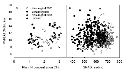
Figure 27. The relationship between RVI/LAI from the MobilLas sensor against total plant N concentration (a) or readings from the Yara SPAD sensor (b). The measurements were taken at GS39 and the LAI was taken at the LAI estimated to a depth of 30 cm.
The RVI spectral index is closely related to the amount of chlorophyll present in the canopy on an area basis. Hence by calculating the RVI/LAI ratio a new index related to the amount of chlorophyll per leaf area unit - or concentration - is obtained. This variable should ideally be correlated to plant N concentration or to the Yara SPAD readings, which are a measure of chlorophyll content. However, there was only a weak correlation between the RVI/LAI indicator and the plant N concentration or SPAD readings (Fig. 27). The correlation coefficients between RVI/LAI and SPAD were 0.24 (P=0.0015), 0.20 (P=0.0126), 0.26 (P=0.0017) and 0.35 (P=0.0001) for Nissumgård 2005, Schackenborg, Nissumgård 2006 and Dybvad, respectively. The weak correlation may partly be due to the problems in accurately estimating LAI at GS39 with the MobilLas sensor and for Schackenborg possibly due to interference of weeds with the RVI measurements.
3.5 Fungicide deposition
3.5.1 Leaf size
The examination of leaf deposition of fungicides in the two experiments involved the measurement of leaf area and leaf weight of the three leaf sections. The leaf area measurements in Table 8 show responses to the nitrogen strategies used in the four experiments. In 2005 differences were significant concerning the flag leaf and the 2nd leaf at Nissumgård, whereas significant differences were seen for all three leaf sections at Schackenborg. It is not surprising that the largest differences found were between the treatments with the lowest and the highest nitrogen supply. Fungicide was applied at an earlier growth stage in 2006 and as a consequence the flag leaf was generally less developed and had a smaller area than the preceding year. Significant differences in leaf area were found at both Nissumgård and at Dybvad and for all three leaf sections in 2006. However, leaf area in plots with the single N application was the largest at both places in 2006. Leaf area in the low N treatment had the smallest leaf area at both locations in 2006.
Table 8. Leaf area (cm²/leaf) of three leaf levels at the four experimental sites.
| Fertiliser treatment | Flag leaf | 2nd leaf | 3rd leaf |
| Nissumgård 2005 | |||
| 1. 160 N split | 28.07 | 29.41 | 19.08 |
| 2. 80 N split | 20.95 | 24.59 | 18.24 |
| 3. 240 N split | 30.81 | 30.78 | 19.81 |
| 4. 160 N once | 26.76 | 29.34 | 20.17 |
| LSD95 | 2.66 | 2.17 | 1.77 |
| Schackenborg 2005 | |||
| 1. 160 N split | 24.27 | 24.56 | 15.79 |
| 2. 80 N split | 18.93 | 21.95 | 15.16 |
| 3. 240 N split | 19.15 | 26.19 | 17.46 |
| 4. 160 N once | 24.03 | 24.96 | 19.58 |
| LSD95 | 1.58 | 2.43 | 1.59 |
| Nissumgård 2006 | |||
| 1. 160 N split | 15.80 | 19.14 | 19.34 |
| 2. 80 N split | 13.92 | 17.89 | 18.36 |
| 3. 240 N split | 16.09 | 18.71 | 18.58 |
| 4. 160 N once | 18.02 | 23.00 | 21.32 |
| LSD95 | 1.75 | 1.86 | 1.53 |
| Dybvad 2006 | |||
| 1. 160 N split | 16.62 | 22.29 | 18.01 |
| 2. 80 N split | 15.42 | 22.06 | 18.20 |
| 3. 240 N split | 16.87 | 22.62 | 18.12 |
| 4. 160 N once | 18.70 | 26.83 | 20.34 |
| LSD95 | 1.56 | 1.27 | 1.15 |
The dry weight of the leaf sections (Table 9) shows a corresponding influence of N supply, with the primary differences for the flag leaf and at the 2nd leaf. However apart from the influence of total N supply, an effect of N timing is seen especially in the 2005 experiments. In both years the two treatments with 160 kg N ha-1 showed a greater dry weight of the 3rd leaf, when N was supplied once. On the other hand it seems that the N supply in these plants was limiting the development of the flag leaf as this leaf section in 2005 was significantly lighter than the flag leaf in the treatment, where 160 kg N ha-1 was applied in a split strategy. In 2006 there were the same difference between the two treatments as in 2005 looking at the 3rd leaf. However, leaf weight of the flag section was not reduced in 2006 in the treatment with a single N application. The difference could be due to the earlier fungicide treatment and leaf area measurement in 2006.
Table 9. Leaf weight (g dry matter/leaf) of three leaf levels at the four experimental sites.
| Fertiliser treatment | Flag leaf | 2nd leaf | 3rd leaf |
| Nissumgård 2005 | |||
| 1. 160 N split | 0.141 | 0.136 | 0.0742 |
| 2. 80 N split | 0.108 | 0.125 | 0.0779 |
| 3. 240 N split | 0.155 | 0.142 | 0.0778 |
| 4. 160 N once | 0.124 | 0.132 | 0.0809 |
| LSD95 | 0.013 | 0.004 | 0.0072 |
| Schackenborg2005 | |||
| 1. 160 N split | 0.137 | 0.143 | 0.0841 |
| 2. 80 N split | 0.115 | 0.145 | 0.0911 |
| 3. 240 N split | 0.163 | 0.156 | 0.0852 |
| 4. 160 N once | 0.132 | 0.148 | 0.0957 |
| LSD95 | 0.013 | 0.011 | 0.009 |
| Nissumgård 2006 | |||
| 1. 160 N split | 0.0877 | 0.103 | 0.0912 |
| 2. 80 N split | 0.0760 | 0.091 | 0.0830 |
| 3. 240 N split | 0.0898 | 0.099 | 0.0879 |
| 4. 160 N once | 0.0961 | 0.116 | 0.0963 |
| LSD95 | 0.0108 | 0.0104 | 0.0094 |
| Dybvad 2006 | |||
| 1. 160 N split | 0.0851 | 0.114 | 0.0852 |
| 2. 80 N split | 0.0777 | 0.111 | 0.0837 |
| 3. 240 N split | 0.0891 | 0.120 | 0.0872 |
| 4. 160 N once | 0.0938 | 0.133 | 0.0901 |
| LSD95 | 0.0072 | 0.007 | (0.0060) |
The specific leaf weight results are shown in Table 10. Nitrogen strategies had significant influence on the specific leaf weight on some of the leaf sections at the two experimental sites in 2005. In 2006 on the other hand, no significant differences in specific leaf weight were seen at any combination of leaf section and location.
Table 10. Specific leaf weight (g dry matter/cm² leaf) of three leaf sections at the four experimental sites.
| Fertiliser treatment | Flag leaf | 2nd leaf | 3rd leaf |
| Nissumgård 2005 | |||
| 1. 160 N split | 0.00503 | 0.00462 | 0.00388 |
| 2. 80 N split | 0.00517 | 0.00514 | 0.00429 |
| 3. 240 N split | 0.00505 | 0.00462 | 0.00392 |
| 4. 160 N once | 0.00465 | 0.00452 | 0.00414 |
| LSD95 | 0.00036 | 0.00013 | 0.00049 |
| Schackenborg | |||
| 1. 160 N split | 0.00564 | 0.00582 | 0.00538 |
| 2. 80 N split | 0.00607 | 0.00662 | 0.00605 |
| 3. 240 N split | 0.00560 | 0.00613 | 0.00489 |
| 4. 160 N once | 0.00551 | 0.00609 | 0.00491 |
| LSD95 | 0.00036 | 0.00097 | 0.00049 |
| Nissumgård 2006 | |||
| 1. 160 N split | 0.00555 | 0.00538 | 0.00472 |
| 2. 80 N split | 0.00547 | 0.00511 | 0.00451 |
| 3. 240 N split | 0.00559 | 0.00527 | 0.00473 |
| 4. 160 N once | 0.00534 | 0.00508 | 0.00453 |
| LSD95 | (0.00028) | (0.00031) | (0.00037) |
| Dybvad | |||
| 1. 160 N split | 0.00513 | 0.00510 | 0.00473 |
| 2. 80 N split | 0.00505 | 0.00503 | 0.00459 |
| 3. 240 N split | 0.00523 | 0.00529 | 0.00482 |
| 4. 160 N once | 0.00504 | 0.00496 | 0.00449 |
| LSD95 | (0.00027) | 0.00016 | 0.00025 |
3.5.2 Leaf deposition
The deposition of tracer on the three leaf sections is shown as deposition per leaf area unit (Table 11). The tracer was applied at an area dose corresponding to 1 mg per cm² horizontal surface. Leaf orientation, however, is not horizontal, but the figure gives an indication that the values in the table are within the expected interval.
There was a large difference in the overall deposition level between the two experimental sites in 2005, and this was primarily caused by differences in deposition values on the flag leaf. The flag leaf is the first “filtering unit” of the spray cloud. The differences between the treatments in deposition per area unit leaf on the flag leaf are supposed to be caused mainly by differences in leaf orientation. In 2005 the two treatments, 80 kg N ha-1 and 160 kg N ha-1 in one application had more erect leaves compared to the two other treatments with split application of 160 and 240 kg N ha-1 and the deposition per area leaf unit on the flag leaf is correspondingly lower on these more erect leaves.
Deposition values on the 2nd leaf and especially on the 3rd leaf at Nissumgård in 2005 show a greater penetration and deposition in the more open crops with a reduced deposition on the flag leaf. The deposition values at Schackenborg were at a much lower level. This is probably caused by the fact that the crop generally was more open and erect. Differences between treatments were smaller at Schackenborg. However, the same influence of crop density on penetration is seen, because deposition on the 3rd leaf is much higher in the open crop fertilized with 80 kg N ha-1 compared to the 240 kg N ha-1 treatment with a much denser crop structure.
Deposition values in 2006 were much more even within the three leaf sections for the four nitrogen treatments at both Nissumgård and Dybvad and no significant differences between N treatments were found. Compared to 2005, differences in leaf orientation between the four nitrogen treatments were much smaller at the time of fungicide/tracer in 2006 at both locations. This is supposed to be the primary reason for the small differences in deposition per leaf area unit between nitrogen treatments in 2006 compared to the preceding year. In all experiments, deposition per unit area decreased from the flag leaf to the 3rd leaf. The decrease seems to be related to crop density.
Table 11. Deposition of tracer (mg BSF/cm² leaf) on the three leaf sections at the four experimental sites.
| Fertiliser treatment | Flag leaf | 2nd leaf | 3rd leaf |
| Nissumgård 2005 | |||
| 1. 160 N split | 0.306 | 0.155 | 0.091 |
| 2. 80 N split | 0.225 | 0.177 | 0.124 |
| 3. 240 N split | 0.288 | 0.154 | 0.077 |
| 4. 160 N once | 0.222 | 0.160 | 0.105 |
| LSD95 | 0.038 | 0.027 | 0.024 |
| Schackenborg | |||
| 1. 160 N split | 0.143 | 0.132 | 0.084 |
| 2. 80 N split | 0.126 | 0.151 | 0.112 |
| 3. 240 N split | 0.165 | 0.157 | 0.070 |
| 4. 160 N once | 0.136 | 0.154 | 0.093 |
| LSD95 | 0.032 | 0.038 | 0.019 |
| Nissumgård 2006 | |||
| 1. 160 N split | 0.238 | 0.245 | 0.157 |
| 2. 80 N split | 0.218 | 0.227 | 0.151 |
| 3. 240 N split | 0.272 | 0.242 | 0.157 |
| 4. 160 N once | 0.237 | 0.212 | 0.135 |
| LSD95 | (0.043) | (0.031) | (0.021) |
| Dybvad | |||
| 1. 160 N split | 0.195 | 0.220 | 0.100 |
| 2. 80 N split | 0.197 | 0.225 | 0.113 |
| 3. 240 N split | 0.209 | 0.195 | 0.102 |
| 4. 160 N once | 0.207 | 0.212 | 0.094 |
| LSD95 | (0.036) | (0.032) | (0.021) |
Table 12 show the deposition of tracer per weight unit of the leaf sections. These results correspond with the values in Table 11.
Table 12. Deposition of tracer (mg BSF/g DM) on the three leaf sections at the four experimental sites.
| Fertiliser treatment | Flag leaf | 2nd leaf | 3rd leaf |
| Nissumgård 2005 | |||
| 1. 160 N split | 60.95 | 33.61 | 23.33 |
| 2. 80 N split | 43.97 | 34.94 | 28.83 |
| 3. 240 N split | 57.04 | 33.05 | 19.16 |
| 4. 160 N once | 47.23 | 35.28 | 25.53 |
| LSD95 | 7.34 | (5.26) | 4.73 |
| Schackenborg | |||
| 1. 160 N split | 25.54 | 22.78 | 15.55 |
| 2. 80 N split | 20.79 | 22.95 | 18.51 |
| 3. 240 N split | 29.49 | 25.34 | 14.20 |
| 4. 160 N once | 24.67 | 25.31 | 18.84 |
| LSD95 | 5.72 | (4.02) | (3.14) |
| Nissumgård 2006 | |||
| 1. 160 N split | 42.96 | 45.69 | 33.42 |
| 2. 80 N split | 40.01 | 44.64 | 33.97 |
| 3. 240 N split | 48.81 | 46.12 | 33.48 |
| 4. 160 N once | 44.60 | 41.76 | 29.50 |
| LSD95 | (8.02) | (6.46) | (4.38) |
| Dybvad | |||
| 1. 160 N split | 38.11 | 43.22 | 21.23 |
| 2. 80 N split | 38.92 | 44.83 | 24.69 |
| 3. 240 N split | 39.64 | 36.06 | 20.57 |
| 4. 160 N once | 41.29 | 42.96 | 20.81 |
| LSD95 | (6.64) | (6.40) | (4.65) |
3.5.3 Soil deposition
Deposition of tracer on the soil surface is shown in Table 13 The values at Schackenborg was influenced by a large population of Poa annua that is supposed to be the primary reason to the difference in absolute deposition level between the two experimental sites in 2005. Although the level is different, the actual order of treatments is the same. Generally the highest soil deposition in 2005 was found in the 80 kg N ha-1 whereas there were small and non-significant differences between the other treatments. In 2006 soil deposit values were again highest at the 80 kg N ha-1 treatment at both locations. However, soil deposition values was lower at both locations, where the normal N rate was applied once compared to the other 3 nitrogen treatments.
Table 13. Deposition of tracer (% of applied) on objects at soil level at the two experimental sites.
| Treatment | Nissumgård 2005 |
Schackenborg | Nissumgård 2006 |
Dybvad |
| 1. 160 N split | 19.0 | 12.7 | 24.7 | 19.3 |
| 2. 80 N split | 33.6 | 20.9 | 28.2 | 22.2 |
| 3. 240 N split | 16.3 | 11.2 | 25.6 | 18.4 |
| 4. 160 N once | 19.2 | 11.9 | 20.6 | 14.1 |
| LSD95 | 5.5 | 3.0 | 3.8 | 4.3 |
3.6 Fungicide deposition at different driving speed
The experiment with application of tracer at different driving speeds showed no significant influence of nitrogen level on deposition of spray liquid on any of the three leaf sections. The primary purpose of the experiment was to investigate whether the application speed influenced the profile of deposition in the crop canopy. The deposition values are given as relative values as there were some problems with absolute values due to different recovery of the two tracers from the plant material. Deposition values on the flag leaf were set equal to 100 and the deposition per area unit on the second and on the third leaf was calculated relative to this value.
Table 14. Relative deposition of spray liquid on three leaf sections at two sprayer speeds, using LD-02 low drift nozzle.
| Speed of application and water volume | ||
| 4 km h-1, 240 l ha-1 | 8 km h-1 120 l ha-1 | |
| Flag leaf | 100 | 100 |
| 2nd leaf | 94 | 58 |
| 3rd leaf | 75 | 39 |
| LSD0.95 | 15 | 11 |
The results in Table 14 show a decreasing deposition of spray liquid per area unit as the spray penetrates the canopy. At 4 km h-1 deposition per area unit on the 2nd leaf was slightly reduced and there was a significantly reduced deposition on the 3rd leaf. However at 4 km h-1 deposition per area unit on the 3rd leaf was still approximately 75% of the value on the flag leaf. At 8 km h-1 deposition per area unit decreased much faster, and there was a significant difference between deposition values on all three leaf sections.
The measurements of deposition of spray liquid on the soil surface in the experiment are shown in Table 15. The results show the deposition values per area unit at the soil surface as a percentage of the applied area dose.
Table 15. Deposition of spray liquid at soil level in winter wheat at GS53 BBCH at two different sprayer speeds and at two nitrogen levels.
| Speed of application and water volume | ||
| Nitrogen level | 4 km h-1, 240 l ha-1 | 8 km h-1 120 l ha-1 |
| 80 kg N ha-1 | 18.0 | 22.7 |
| 160 kg N ha-1 | 13.5 | 15.6 |
| LSD0.95 | (5.1) | 6.5 |
There was no significant influence of speed on soil deposition values. This is in accordance with earlier results by Jensen and Spliid (2005) comparing soil deposition values in winter wheat at the same sprayer speeds as in this investigation. At 4 km h-1 there is a tendency towards a lower soil deposition value at the high N rate, and at 8 km h-1 there is a significant difference.
Version 1.0 January 2008, © Danish Environmental Protection Agency