Dry deposition and spray drift of pesticides to nearby water bodies
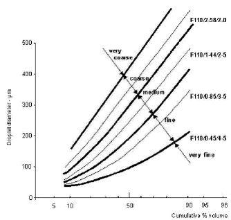
3 Spray drift3.1 Spray properties3.1.1 Equipment 3.1.2 Drop size distribution 3.1.3 Droplet velocity 3.1.4 Droplet movement 3.1.5 Boom height 3.1.6 Air-assistance, shielding etc. 3.1.7 Factors influencing drop generation 3.1.8 Atomiser systems currently used in Denmark 3.1.9 Recommendations for research/development 3.1.10 Review of spray drift experiments 3.2 Application technique 3.2.1 Droplet size 3.2.2 Boom height 3.2.3 Drift reducing equipment 3.2.4 Driving speed 3.3 Climatic factors 3.3.1 Wind speed 3.3.2 Humidity and temperature 3.3.3 Spray-free zone 3.3.4 Potential drift reduction exploiting technical possibilities 3.1 Spray properties3.1.1 EquipmentPesticides are applied in dose rates ranging from a few grams formulated product per hectare. Such small amounts cannot be applied with the equipment normally used for pesticide application. Before pesticides are applied they are generally diluted with water in order to obtain a liquid amount that can be distributed evenly on the sprayed area/crop with the aimed dose of pesticide. Pesticide application under field conditions is generally carried out with different types of tractor-mounted or self-propelled sprayers. Boom sprayers are used in annual crops with a limited height and in perennial crops in the establishment stages. This includes all agricultural crops, field grown vegetables, plantations of bush fruit and Christmas trees. Boom sprayers consist of a vertical boom placed perpendicular to the driving direction. The boom is equipped with atomisers along it which have two functions. Different boom sprayers with alternative atomiser systems such as the air-sprayer from Danfoil and the Twin-fluid nozzles have a small percentage of the market. The droplet characteristics from these systems are somewhat different than that from hydraulic nozzles, and also the initial droplet velocity may deviate. 3.1.2 Drop size distributionDue to the construction of the hydraulic nozzles a mixture of different droplet sizes are produced. The droplet size or more correct droplet sizes can be characterised by different methods. As a minimum, the VMD (Volume Median Diameter) is normally given. VMD for a nozzle at a given pressure indicates the droplet size dividing the spray liquid in such a way that 50% of the liquid volume will atomise into droplets smaller than the VMD, and 50% will atomise into droplets larger than the VMD. VMD is often denoted D50. Additional values describing the variation in droplet sizes are D10 and D90, which denotes the droplet sizes dividing the spray liquid in such a way that 10% of the liquid amount will atomise into droplets smaller than D10 or larger than D90. In spray drift studies a close correlation between droplet size and spray drift is seen and a big proportion of this correlation can be explained by the fraction of droplets with a diameter below 100 µm (Hobson et al., 1993) (Lagerfelt, 1988). Because of this, the percentage of the spray liquid atomised into droplets below this size is often given. Another classification system, which describes the droplet size distribution with a single notation into five categories has been developed (Doble et al., 1985), (Southcombe et al., 1997). The classification divides the hydraulic nozzles into the categories very fine, fine, medium, coarse and very coarse (Fig. 18). Figure 18. Droplet size distribution of nozzles according to the BCPC classification. This is possible because a change in droplet size (MVD), generally, doesn’t change the shape of the droplet size distribution. A change in droplet size moves the distribution of droplets towards another size class. Droplet size measurements are dependent on the technique used for the measurement. In order to eliminate this problem, the BCPC classification includes seven reference nozzles. Four of these are threshold nozzles describing the border between the five categories, and three describes characteristic “Fine”, “Medium” and “Coarse” nozzles. The commonly used hydraulic flat fan nozzles fit well into this classification, whereas some special nozzles do not. 3.1.3 Droplet velocityWhen the spray liquid leaves the nozzle the typical velocity is approximately 20 m s-1 according to Elliott and Wilson (1983). This initial velocity is lost after a distance due to air resistance. Depending on the size, the droplets then reach the sedimentation velocity, in different distances from the nozzle. The sedimentation velocity is the velocity due to gravitation and air resistance. The sedimentation velocity of different droplet sizes is shown in Table 4.
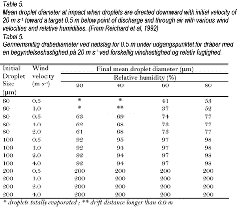
The table also includes the corresponding stop distance of the smallest droplet sizes. The stop distance is defined as the distance the droplet travels if it is projected horizontally with an initial velocity of 20 m s-1. During application with field sprayers, the spray is normally emitted vertically downward from the boom/nozzle. At a distance below the nozzle approximately equal to the stop distance, the droplet will approach its sedimentation velocity. Droplets with a small diameter have a relatively low weight in proportion to their surface and air resistance therefore exerts a greater influence than on larger droplets. As a result small droplets loose their initial velocity fast and the sedimentation velocity of these droplets are low. The consequence is that small droplets are influenced by wind and turbulence in the field for a much longer period than larger droplets. The difference between different droplet sizes is, however, more limited than the figures in Table 4 indicate. This is due to the fact that when the spray leaves the nozzle, a downward pointing air current is created. Another aspect discussed by Reichard et al. (1992) is the influence of humidity and wind on droplet size during the travel from nozzle to target. Some results of simulations from this work are shown in Table 5.
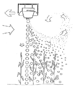
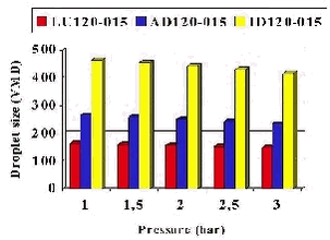
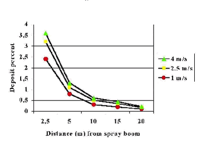
The simulations indicate a much greater change between initial and final droplet sizes during the flight for droplets with an initial small droplet size. A water droplet with an initial size of 60 µm was only 37 µm in diameter when it reached the target after travelling through wind with a velocity of 1 m s-1 and 60% relative humidity. This change in droplet size corresponds to a much larger change in volume as 76.6% of the initial volume was lost. For the same conditions 100 and 200 µm diameter droplets lost 8.7 and 0% respectively, of their initial volumes during flight. Smaller droplets lose a greater proportion of their volume faster due to evaporation because they have larger surface area to volume ratios than larger droplets. The smaller droplets are therefore potentially more driftable due to different factors. This is also reflected in a number of spray drift investigations, where a close relationship between percentage of droplets with a diameter below 100 µm and measured spray drift is shown (Hobson et al., 1993) (Lagerfelt, 1988). The droplet velocity is dependent on pressure and low-drift nozzles, which are developed to reduce spray drift by creating a coarser atomisation, have a pre-orifice, which reduces pressure at the outlet. Measurements has shown that the droplet velocity from low-drift nozzles is reduced compared to standard flat fan nozzles (Miller, 1999). This means that the potential spray drift reduction from low-drift nozzles is less than would be expected only by considering the droplet size distribution from the low-drift nozzle and the standard flat fan nozzle. Some alternative atomiser systems exist, where the droplet velocity at the nozzle outlet deviates from the approximate 20 m s-1 of standard flat fan nozzles. These include the Danfoil air-sprayer where air-pressure is involved in droplet formation giving the droplets a higher velocity than from standard flat fan nozzles (Lund, 1997). 3.1.4 Droplet movementAfter the spray liquid has left the nozzle and the droplets have been formed they are subject to different forces before they reach the target. Gravitation and air resistance are discussed elsewhere. The droplets are, however subject to other forces before they reach the target. During the atomisation, the spray liquid is projected vertically downwards, but at the same time the field sprayer is moving forwards typically with a driving speed close to 2 m s-1. When the spray liquid leaves the nozzle, the movement of the spray cloud accelerates the air surrounding it into a motion parallel to the spray cloud. The induced downward aircurrent creates a vacuum around the nozzle. At the front side of the nozzle the depression is filled by air coming in when the boom is moved in the driving direction. The vacuum behind the nozzle is compensated by air being sucked up from behind the spray cloud to maintain a pressure equilibrium (Fig. 19). The droplets on their way to the target experience the forward speed as wind coming in from the front. Depending on their momentum they are deflected more or less from their vertical trajectory. The smaller the momentum the more is the direction bent towards the rear of the spray cloud. The droplets which are sucked out of the spray cloud in this manner are caught by the upward directed air current behind the nozzle forming trailing vortices of primarily small droplets behind the nozzle. By this process a proportion of the primarily small droplets will be placed above the height where they were released from the nozzle. The aerodynamic properties of the spraying nozzle itself can therefore be an important factor influencing the spray drift potential. Figure 19. Droplet movement. 3.1.5 Boom heightFrom Table 5 it appears indirectly that boom height has a major influence on the drift potential. When the sprayer is equipped with hydraulic flat fan nozzles with a spray angle of 1100 the recommended boom height is 40-50 cm. Using this boom height, droplets with a diameter larger than 200 µm will reach the spray target with some of their initial velocity retained. The time used to pass from nozzle outlet to target is then limited. Small droplets with a diameter below 50 µm on the other hand loose their initial velocity a few centimetres below the nozzle outlet. With the very low sedimentation velocity of droplets in this size class, the time interval these droplets spend on their way to the target is long and this makes them very susceptible to wind drift. Droplets with diameters ranging from 50-200 µm are transferred a part of the way from nozzle to target before they reach their sedimentation velocity. An increased boom height means that the smallest droplets below 50 µm are influenced by the natural wind conditions for a longer time period. Increasing the boom height also means that an increasing proportion of the droplets in the medium size class 50-200 µm looses their initial velocity farther away from the target and becomes potentially drift prone. In a paper by Reichard et al (1994) examples of the influence of changes in boom height on the transport of different droplets sizes are calculated. From these it appears that it is primarily the drift potential of droplets in the group below 100 µm that are influenced by changes in boom height. From an actual spray drift measurement a doubling of the drift values were found when the boom height was raised from 50 to 70 cm (Miller, 1988). When using hydraulic flat fan nozzles a double spray pattern overlap is desired in order to obtain a good distribution. Nozzles with a wide spray angle achieve the double overlap of the spray pattern at lower boom height than those with a narrow spray angle. With a 110° spray angle double overlap is achieved at 35 cm boom height whereas the boom height has to be raised to 60 cm with 80° spray angle. The use of nozzles with a symmetrical spray angle and intended double overlap means that a small area outside the field will be sprayed directly by the outermost nozzle. In order to avoid this, different types of border nozzles with an asymmetric spray pattern are produced. A change to this nozzle type at the outermost position can reduce spray drift especially in the first couple of meters from the treated field edge, whereas the influence is small at larger distances from the field edge (van de Zande et al., 1995). Use of this type of nozzles is therefore especially interesting in order to avoid damage to nearby crops, watercourses and other susceptible areas. During field spraying the boom height will vary due to roughness of the spray tracks. When the boom height deviates from the height where double overlap of the spray pattern is achieved, an uneven distribution of the spray will occur. The variation in distribution of spray liquid will be greater when the boom height is below the optimal height compared to a boom height that is above the optimal. Until technical developments has eliminated boom movements during field applications and the associated variation in spray distribution, this will be a limiting factor towards how low a boom height that can be used under practical field spraying. 3.1.6 Air-assistance, shielding etc.Different drift-reducing solutions to traditional field spraying equipment have been developed. One technology is to shield the spray in order to avoid the influence of the natural wind on the small droplets. Shielding of the individual nozzles (Maybank et al, 1990) as well as a shield covering the entire boom (Wolf et al, 1993) has been constructed. Shielding devices where part of the headwind is used to compensate the depression behind the nozzle has also been investigated (Ozkan et al, 1997). Effective drift reducing commercial shielding devices have been available for row application kits a number of years (Jensen and Spliid, 1998). For boom sprayers the technology seems not fully developed yet although commercial possibilities are available. Another technology is the use of air- assistance to conventional hydraulic nozzles. The purpose of the air-assistance is to counteract the effects the driving speed and the vacuum behind the nozzles exert on the droplets. The concept is to create an air-curtain behind the nozzles that will force small droplets back to the spray cloud if they have been sucked out (ICI, 1990). Furthermore the air-assistance will increase the droplet speed reducing the time to reach the target. 3.1.7 Factors influencing drop generationIn hydraulic nozzles the main factor determining the droplet size distribution is the nozzle size. Changes in the liquid pressure exert a minor effect as shown in the Fig. 20. Pesticides are normally formulated with additives such as surface-active ingredients, oil additives and emulsifiers. The function is to increase the deposition and retention of the droplets on the target, and to improve the uptake of the pesticide. The changes in physico-chemical properties of the spray liquid also change the droplet formation from the nozzle. The way the droplet formation is changed varies from additive to additive and interactions between nozzle types and additives are seen (Ellis et al., 1999). In the same investigation it was demonstrated that additives can influence both droplet size distribution and droplet velocity. Compared to the droplet formation with pure water some additives reduce the MVD whereas others increase the VMD but no clear correlation to physico-chemical properties such as surface tension are seen (Chapple et al., 1993). Some additives are marketed as drift retardant chemicals. These additives can reduce drift (Ozkan et al., 1993) (Western et al., 1999) because they increase the VMD value. Figure 20. Influence of nozzle pressure on droplet size (VMD) of Lechler flat fan nozzles (LU= traditional flat fan, AD=low-drift, ID=air-inclusion nozzle). 3.1.8 Atomiser systems currently used in DenmarkBoom sprayers are used for applications in annual crops and in perennial crops in the establishment stages. This includes all agricultural crops, field grown vegetables, plantations of bush fruit and Christmas trees. Alternative sprayers are used in orchards but will not be discussed here. Boom sprayers consist of a vertical boom placed perpendicular to the driving direction. The boom is equipped with atomisers along it. The typical atomisers used on field sprayers in Denmark are different types of flat fan nozzles, typically with a spray angle close to 1100 and used at a recommended boom height of 40-45 cm. When classified according to the BCPC classification system almost all traditional hydraulic nozzles recommended and used are in the “Fine” or “Medium” classes. This technique probably accounts for more than 90% of the applications with boom sprayers in Denmark. Systems which include air-assistance to hydraulic nozzles (Hardi Twin and others) the air-spraying system from Danfoil, and other systems occupies a small percentage of the market. 3.1.9 Recommendations for research/developmentThe atomisation process in hydraulic nozzles produces a broad spectrum of droplet sizes around the VMD value. Research has not documented one single droplet size to be the optimal. The different droplet sizes produced from hydraulic nozzles have different advantages and disadvantages due to their properties and generally supplement each other. As a consequence hydraulic nozzles can be used for all applications with a generally robust result. Small droplets have the advantage of better deposition characteristic whereas larger droplets have a better ability to penetrate into the crop. The smallest droplets, however, with sizes below 100 µm are very difficult to control under field conditions with conventional sprayers. They constitute a minor proportion of the total volume atomised, whereas they are responsible for most of the spray drift problems encountered according to studies discussed elsewhere. From the point of view of biological efficacy droplets below 100 µm are probably dispensable if they could be avoided without changing the total droplet spectrum towards a coarser atomisation. This seems, however, to require another atomisation technology than used in hydraulic nozzles. Hydraulic nozzles with a very coarse atomisation such as air-inclusion nozzles have been marketed in the last few years. Their drift reducing properties are obvious due to the coarse atomisation and have been demonstrated in a number of studies. In general, however, smaller droplets are considered biologically more effective than larger ones. From an agronomic as well as from an environmental point of view, it is important that the biological efficacy of pesticides applied with alternative nozzle types is maintained. It is, therefore, necessary to find and define the areas where drift-reducing nozzles can replace traditional flat fan nozzles and maintain biological efficacy, since an effective application method allows the pesticide dose to be reduced to a minimum. Such investigations are in their early stages at the moment (Jensen, 1999). 3.1.10 Review of spray drift experimentsDuring the last 20 years a large number of spray drift investigations have been published. The field experiments include all aspects of application techniques, such as nozzle types and pressure, boom height, travelling speed and drift reducing equipment such as shielding devices and air-assistance. They also include investigations on the influence of climatic factors, and especially wind speed. Different techniques have been used as an international standard is not yet agreed on nor implemented but a proposal is at the time being discussed (Miller et al. unpublished). The general way to carry out field experiments investigating spray drift is to drive with a tractor-mounted sprayer in a spray track with the wind direction perpendicular to the driving direction. The spray drift is then measured downwind in different distances from the sprayed area. Measurements of sedimentation drift are carried out on horizontal objects placed on or near the ground level. Sometimes measurements of airborne drift in different heights on masts placed a few metres from the sprayed area are included. This is done with passive or active samplers. Generally, however, calculation of total drift or total spray account (deposition+evaporation+drift) is seldom done. This is also because the total drift is very dependent on the size of the field sprayed as spray drift often is defined as spray caught outside the sprayed field. As most of the drift sediments very close to the sprayed track, the outermost track/tracks of a field contributes by far the largest proportion of the total drift whereas drifting droplets from spray tracks inside the field causes a displacement and uneven distribution within the field, but contributes very little to drift out of the field. Arvidsson (1997), however, reviewing drift experiments reported a total drift of 5% as a mean from a number of studies where drift was measured outside a 12 meters wide area and the total calculated drift in his own investigations varied from a few percent up to 11%. Results from drift investigations are, considering the sedimenting part of drift, normally presented as a percent of the applied dose rate. The amount of drift as a function of distance from the sprayed area fits an exponentially decreasing function as can be seen from Fig. 21.
Figure 21. Deposited spray liquid (%) as a function of the distance from the spray boom for three wind speeds. Spray nozzle TeeJet 11001, spray pressure 2.5 bar (after Lagerfelt, 1988). Probably the most intensive study comes from Germany (Ganzelmeier et al., 1995) where a large number of drift experiments has been carried out in field crops and in orchard crops such as blackcurrants, apples etc. The results from these studies, the so-called Basic Drift Values, constitute the basis for the approval of sprayers in Germany. They also constitute the basis for the determination of buffer zones to surface water in the pesticide approval procedure in many countries including Denmark. The determined mean values and the calculated 95% percentiles calculated for field crop spraying are shown in Table 6. It can be seen that the drift values are approximately halved every time the distance is doubled. These values has recently been updated with a larger number of drift studies but the 95% percentile values are not yet available (Rautmann, pers comm), and only minor changes in the level of the mean drift values have occurred. The values from the German work in field crops comes from trials carried out under continental conditions with wind speeds ranging from 1 – 3 m s-1 and with the use of medium atomising spray technique. Although finer atomising nozzles are used under Danish conditions drift values found are in the same order of magnitude at similar wind conditions (Jensen and Kirknel, 1997). However, a coastal climate as in Denmark is characterised with more windy conditions especially in the middle of the day. Weather conditions with wind speeds in the range 3 - 4 m s-1 during application seems to be reasonable assumption under Danish conditions. Taking into consideration the influence of wind speed on spray drift described in 4.3.1, the 95% percentile values in Table 6 seems to be a reasonable estimate for the average spray drift under Danish conditions. These values are used as mean spray drift values in the decision support system developed in the project “Pesticides in surface water”. The use of larger spray drift values for Danish conditions is supported by data from a larger Dutch investigation (van de Zande, pers comm). The wind conditions in the Netherlands and in Denmark are more comparable and the general impression for Dutch conditions is that the spray drift values are significantly higher than the BBA values. In the following, results from studies investigating the influence of different factors on spray drift are reviewed. Table 6. Statistical evaluation of spray drift in field crops (early and late growth stages) in the study by Ganzelmeier et al. (1995). The figures are mean values and 95% percentiles shown as a percentage of the applied dose in increasing distance from the sprayed area. The 95% percentile is used as a mean value for Danish wind conditions in PestSurf. Tabel 6. Statistisk vurdering af drift i markafgrøder (tidlige og sene vækststadier) i Ganzelmeiers et al. (1995) studie. Tabellen viser gennemsnitsværdier samt 95% percentiler af afdrift som procentdel af den udsprøjtede dosering i stigende afstand fra det sprøjtede område. 95% percentilen er anvendt som en gennemsnitlig afdriftsværdi for danske vindforhold i PestSurf.
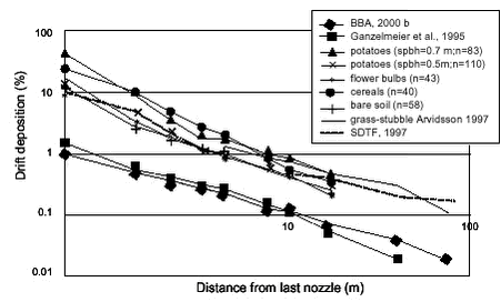
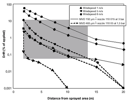
Figure 22.Effect of crop type and environmental circumstances on spray drift (50% percentiles based on measured data), originating from different sources (from van de Zande et al., 2002). 3.2 Application technique3.2.1 Droplet sizeDroplet size distribution of the nozzles used has a major influence on spray drift as can be seen in Fig. 23, which is based on simulations by Kaul et al (1996). These figures are in agreement with field experiments comparing drift from coarse/very coarse air-inclusion nozzles and traditional fine/medium flat fan nozzles. In a study by Taylor et al (1999) a reduction in sedimentation drift of around 90% were found using air-inclusion nozzles compared to standard flat fan nozzles. Figure 23. Influence of droplet size on simulated drift under different wind conditions (after Kaul et al., 1996). 3.2.2 Boom heightThe effect of changes in boom height on potential drift and the reason to the large influence is described above. From actual experiments a steep increase in drift is seen when the boom height is increased above the normal recommended 50 cm (Arvidsson, 1997; Miller, 1999). 3.2.3 Drift reducing equipmentShielding devices has successfully been developed for band spraying equiment in row crops. In field experiments a reduction in spray drift above 90% has been achieved when band application kits are shielded (Jensen and Spliid, 1998; Porskamp et al., 1997). Different types of shielding devices are also developed for boom sprayers, but the drift reduction obtained is not as high as with the solutions for row crops. The typical drift reduction found in experiments with shielding devices to boom sprayers is in the order of 50 percent (Huijsmans et al., 1997). The function of air-assistance in reducing the drift is described above. Commercially solutions have been available for more than ten years in different versions. It is not all types of air-assistance that reduce spray drift (Jensen and Kirknel, 1997; Arvidsson, 1997) but the air-assistance according to the Hardi Twin systems has in general reduced the drift. In this system, nozzles and air can be angled +/- 300 from the vertical but the angling of the air-current is fixed to the angling of the nozzles and the air therefore always follows the droplets the last part of the travel to the target. The effect of air-assistance according to the Hardi Twin systems also varies between studies. Porskamp et al (1997) found drift reductions varying from 45-79% when air-assistance was used compared to the same application without the use of air-assistance. The danish experiences with spray drift when using the Hardi Twin system is in accordance with the Dutch results (Jensen and Kirknel, 1997). Specially designed nozzles (off center nozzles, border nozzles with an asymmetric spray pattern) placed as the outermost nozzle on the boom during application near the edge of the field can decrease the spray drift to the adjacent zone with 20-40% (van de Zande et al., 1995). 3.2.4 Driving speedWhen the driving speed is increased, the droplets experience a stronger force and the airflow due to this increased forward motion is responsible for the detrainment of droplets from the spray structure. In the same time, boom variations is more likely to increase with increasing speed. Together this increases the drift potential. A small increase in driving speed can cause a high increase in spray drift. Miller and Smith (1997) measured a 51% increase when travel speed was raised from 5 to 8 km h-1 and Taylor et al (1989) found a 90% increase in spray drift when speed was increased from 7 to 10 km h-1. 3.3 Climatic factors3.3.1 Wind speedWhen the wind speed is below 0.5 to 1 m s-1, the direction is often diffuse. At wind speeds above 1 m s-1 spray drift increases more or less linearly with wind speed which has been shown both under field conditions (Hobson et al., 1993; Gilbert and Bell, 1988) and in wind tunnel experiments (Sarker and Parkin, 1995). According to Jørgensen and Witt (1997) spray drift investigations carried out at different wind speeds can be normalized by dividing the measured drift with the factor (wind speed in m s-1- 1m s-1). This is equal to a 100% increase in drift when wind speed increases from 2 to 3 m s-1. 3.3.2 Humidity and temperatureThe effect of these factors is difficult to quantify in field experiments. Some analysis of the influence of these climatic factors on spray drift under field conditions was done by Arvidsson (1997) but otherwise the influence have been simulated as shown earlier in the report. The volatilisation conditions during the application constitutes according to Kaul et al (1996) one of the most important drift influencing factors when considering airborne drift, whereas the same authors rank volatilisation conditions as less important concerning sedimentation drift. This is in accordance with what would be expected from the calculations shown in Table 5. 3.3.3 Spray-free zoneThe sharply decreasing spray drift measured in increasing distance from the edge of the sprayed field means that spray drift can be reduced by leaving a buffer zone or a spray-free zone in the field. A non-cropped spray-free zone of 2.25 m reduced the deposition by 70% on the strip of 1.5-6 m from the border of the field (Porskamp et al., 1995).The highest effect of a spray-free zone is obtained if either crop or another type of vegetation is present in the spray-free zone (van de Zande et al., 1995). 3.3.4 Potential drift reduction exploiting technical possibilitiesIn the previous section the influence of different factors evaluated separately was described. The combined influence of different factors on spray drift will be additive and can be calculated from the influence of the individual factors. If different combinations of drift reducing techniques/factors are combined large reductions in spray drift can be achieved compared to a standard application with a technique that doesn’t take the drift aspect into consideration. This has also been demonstrated experimentally by Holterman and van de Zande (1996), who obtained a drift reduction varying from 90-98% depending on wind speed during the experiment. The result was obtained combining low-drift nozzles and the use of border nozzle with a reduced boom height and a spray-free zone of 1 meter. Taylor et al. (1999) demonstrated that drift could be reduced with 95-97% when the standard equipment was exchanged with coarse air-inclusion nozzles used in combination with air-assistance according to the Twin principle and eventually with the use of border nozzles. |
|||||||||||||||||||||||||||||||||||||||||||||||||||||||||
