|
Autonomous Weeder for Christmas Trees – Basic Development and Tests 3 Requirements and system concept
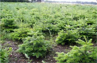
Christmas trees may be considered as an agricultural crop as they are mostly grown on ordinary farmland in rows 1.2 m apart with 1.2 m spacing within the row (Fig. 3.1). The young trees are planted in stands when they are about 20-30 cm high. For the first two years weeds can be controlled by use of long-finger harrows as the young trees are supple enough to withstand the harrows but after that, when the first branches have developed, this method will cause excessive damage and other methods are needed. In the case of Normann fir the first branches develop very close to the ground, but after a few years these branches are removed to restrict top growth of the trees in order to get more homogeneous shapes.
Fig. 3.1. Normann firs in a typical stand. 3.1 Design requirementsThe main requirements for the ACW were defined in the feasibility study (Have et al. 2002) and are shown in Table 3.1. In addition the ACW should handle the trees gently during the 3 weeks from mid May when the shoots are very sensitive to damage. Also it might be relevant to consider so-called negative obstacles (holes or tracks). 3.2 System conceptTo meet these requirements the recommendations made in the feasibility study was followed, i.e.:
Table 3.1 Christmas tree plantation parameters and requirements chosen for the ACW development.
3.3 Choice of vehicle conceptOn basis of the above system requirements a range of methods were considered and evaluated in terms of advantages and disadvantages. This led to the choice of a small vehicle that can move between the trees and cut the weeds close to tree trunks beneath the branches (Fig. 3.2). 3.4 Plantation mappingThe positions of individual trees were measured by means of an RTK GPS ranging pole equipped with a special shoe and antenna arm to ensure that it was placed precisely above the tree trunks (Fig. 3.3). The locations were stored in the hand held data logger and used afterwards to construct a tree map as shown in Fig. 3.4. 3.5 Route plan generationThe tree map was used to define a suitable vehicle route plan (fig. 3.5) in the form of waypoints (one for each tree) along the middle of the inter-row strip. Additional waypoints were defined at the headlands to connect to the next inter-row strip. Each waypoint was defined by its absolute geo-position (Northing and Easting in UTM), and had associated information for control of the rotor cutter (park, idle or active near trees). This information was stored as a text file and arranged sequentially in the route plan.
Fig. 3.2. Sketch of the chosen weeder concept. The vehicle should follow the predefined route plan between the rows, while positioning the rotor cutter to cut the weeds around the trees in the intra-row area. This concept would make it possible to leave the weeds between the rows uncut for improvement of the biodiversity. A future commercial vehicle could be designed with a cutter on both sides to increase capacity.
Fig. 3.3. Schematic diagram of the rig used for measurement of the tree positions. A program called XMAS, was written in C, to import data from the Trimble Geomatics Office (raw GPS data) or corrected data from Excel and help to generate the route plan. The vehicle and plantation parameters were configured in a C-file. With regular fields this system could generate a route plan almost automatically. This method was used both for the plantation model at the Taastrup campus and for the Christmas tree plantations. Another route planning tool used was AgroNav Plan from GEOTEC, which was primarily used as an aid for controlling autonomous tractors (Blackmore and Griepentrog et al. 2004). It is a graphical tool that allows the user to construct a route plan interactively. It uses Autodesk Map 5 (www.autodesk.com) as the “graphical engine”. An inconvenience is however that UTM-coordinates are used on the ACW, which makes it necessary to convert UTM to WGS84 in AgroNavPlan and then after definition back to UTM. This was done by the program KMSTrans available from “Kort og Matrikelstyrelsen” (www.kms.dk, version November 2, 2002). When this method was used for generation of route plans for the ACW the “Power Take Off” code was used for the cutter clutch while the “Hitch Point Lift” code was used for cutter arm positioning.
Fig. 3.4. Sketch of a plantation map showing the borders, numbered tree positions, route plan and docking station, i.e. the place from where the ACW operation is started and stopped after completion.
Fig. 3.5. Typical route plan applied during the experiments. The ACW had to travel back and forth along each row as this model was designed to cut weeds only to one side at a time. The turning circles were offset laterally in order to have a smooth approach to the next inter-row strip. The thin lines, originating from the vehicle track, symbolize the cutter arm, when the cutter is activated. The route plan was made up of waypoints, typically 1.2 to 3 m apart, thus the trace shown is not the connecting lines of these points, but the expected path of the ACW (mainly determined by turn radius) given the switch distances (tolerances) specified for each waypoint. 3.6 Control system developmentThe development of the ACW control system was done in the programming and simulation tool: Simulink from MathWorks (http://www.mathworks.com) as described in (Bak et al., 2004). The application of this software was chosen because it allows modelling, simulation, and analysis with focus on functionality and interfaces in an abstract form that represents the actual programming tasks. Simulink also provides executable graphical models for specifying and implementing embedded software, and it supports automated embedded code creation. This allows programs to be generated automatically and subsequently executed in real-time on the platform computer. In the present project the Simulink software was used to build a model of the vehicle and the control system. This model was then used to simulate the functionality of the different elements and the whole system until it was found to work satisfactorily. Finally the vehicle model was replaced by the real vehicle and tested physically. As part of the model a system for storage of parameter values during the tests was developed. This proved to be very useful for error detection and correction.
|