|
| Front page | | Contents | | Previous | | Next |
Autonomous Weeder for Christmas Trees – Basic Development and Tests
4 Weeder platform development
To minimise trivial and time demanding work on developing a new weeding platform, it was decided to adapt an existing lawn mower with the necessary characteristics to work in a Christmas tree plantation.
4.1 Platform selection and modification
On the basis of the concepts described in section 3 the following requirements were specified: A 4-wheel platform (2-wheel drive, 2-wheel steered, and a wheel diameter of min. 25 cm), a speed range of
0.4 –2.0 m/s, a turning radius less than 1.5 m, a ground clearance greater than 200 mm, a width of less than 750 mm and a length of less than 1500 mm, and equipped with an electrical system comprising
alternator, battery and starter.
The market for lawn mowers of this type was investigated and the vehicle chosen was a Stiga Garden Combi (Fig. 4.1), which fulfilled all the requirements. This platform has a width of 700 mm, a length of
1400 mm and is powered by a 9 kW petrol engine through a V-belt drive and a 5-speed gearbox. At 1800 RPM (the chosen engine speed) the vehicle would travel with a forward speed of 0.30, 0.58,
0.84, 1.08, and 1.42 m/s. and a rearwards speed of 0.49 m/s. The vehicle has front wheel steering, an axle distance of 950 mm and a minimum turning radius of about 1050 mm measured at the rear axle
centre. This platform also has alternator, battery, and electric starter.
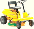
Fig. 4.1. The Stiga Garden Combi lawn mower used as platform for the experimental ACW.
The driver's seat and the steering wheel console were removed to give space for the control components and GPS-antenna (Fig. 4.2, left). Also the 700 mm diameter standard rotor cutter unit was replaced
by a new cutter mechanism consisting of a 320 mm diameter rotor cutter unit (Stihl), which was mounted on an arm that could be moved between the trees. This new cutter rotor was powered through a
twisted V-belt drive and a flexible driveshaft from a hand held rotor cutter (Stihl).
4.1.1 Vehicle cover and protection skirts
To protect the Christmas trees from damage during operation the ACW was shielded on the sides by removable aluminium screens as shown in Fig. 4.2, right, and Fig. 6.6.
4.1.2 Vehicle control actuators
The control of the vehicle was facilitated through 6 linear 12 V electric actuators (Fig. 4.3 and 4.4) that were mounted between a frame fixed on the top of the vehicle chassis and the engine throttle wire,
steering rod, gearshift lever, clutch/brake lever, rotor cutter arm and rotor cutter clutch (V-belt) respectively. The actuators differed in terms of length, operation speed and force in order to match with the
requirements. All of them had built in potentiometers that delivered a feed back voltage proportional with their extents to the control system.
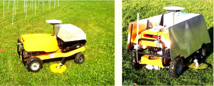
Fig. 4.2. The experimental, autonomous Christmas tree weeder configured with the power unit at the rear end, the control system at the front, the GPS antenna in the middle and the rotary cutter unit between the axles below the chassis. On the picture to the left the vehicle is shown next to the model plantation at campus where the Christmas tree positions were indicated by ground fixed, white plastic tubes. For weeding in the real Christmas tree test plantation the vehicle was shielded with side screens in order to minimise tree damage (right).
Fig. 4.3. The Linak actuator LA 12, which was powered by a 12 V DC motor through a worm gear.
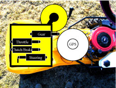
Fig. 4.4. Arrangement of the four Linak actuators for control of the vehicle operation.
4.2 Weed cutter selection and development
As defined in the previous feasibility study (Have et al. 2002) the weed cutter unit should be able to:
- Cut weeds in a band of about 40 cm around each tree
- Cut the weeds at a distance less than 3 cm from the tree trunks
- Avoid excessive injury of trees
- Be able to work beneath the lower tree branches, which often are located only 15 cm above the ground
- Leave the stubble less than 5 cm high
- Follow the ground in uneven terrain
- Be parked beneath the machine chassis free of the ground during turning and transport.
In order to accomplish this, the design shown in Fig. 4.5 and 4.6 was developed.
The cutter rotor could be engaged by use of a V-belt clutch, which was activated by a LINAK actuator. During operation the cutter unit was operated at a speed of about 3800 RPM, which corresponded
to a peripheral speed of about 54 m/s.
Fig. 4.5. Cutter arm suspension (Top view). The cutter arm is connected to the chassis in the shown pivot point and pulled out into its outermost position by the spring. If the cutter hits a solid object, e.g. a
tree trunk, it will be pushed back against the spring force. The outermost position of the arm can be set by the LINAK actuator to have a proper overlap to the strip cut from the other side of the row. The
same actuator was used to position the cutter relative to the trees when operated in the active mode. Also it was used to park the cutter arm below the chassis for transport.
Fig. 4.6. Cutter arm suspension (side view). The arm is fixed onto a height adjustable pivot axel and can deflect upwards in case it hits an obstacle (i.e. in case of uneven ground the drag shoe formed by the bump below the rotor causes the cutter arm to deflect upwards).
| Front page | | Contents | | Previous | | Next | | Top |
Version 1.0 November 2005, © Danish Environmental Protection Agency
|