|
Autonomous Weeder for Christmas Trees – Basic Development and Tests 6 Results
This chapter describes the results of adaptation of sensors, simulation of control components, accuracy of vehicle operation in relation to route plans and operation in the plantation model and a Christmas tree plantation. 6.1 Sensor capabilities and reliabilitiesThis section describes the results obtained during the work on integrating the RTK GPS, the tilt-meter and the laser range scanner. 6.1.1 RTK GPSStatic tests of the RTK GPS at an open location showed high reliability and high accuracy (±1-2 cm in the horizontal plane). However, when attached to the ACW during different operations conditions, the quality of the signal dropped if the number of satellite contacts became too small (less than 5). This happened mostly when the vehicle was close to larger trees or other high structures. When happening it was recognised by the supervisory logic system and the engine was stopped automatically, just as it should (section 5.5.4). 6.1.2 Tilt meterAs the GPS-antenna was placed above the vehicle it translated laterally as the vehicle rolled over uneven ground. This led to errors in the measurements of the vehicle position, which of course had a disturbing effect on the tracking control. To correct for this a tilt-meter was integrated as described in section 5.4. However, this instrument was found to be of little use, as it was very sensitive to the vibration characteristics of the ACW. This problem needs to be solved, but was not prioritized in the project because of lack of time. 6.1.3 Laser scannerThe preliminary trial of the laser range scanner in the laboratory showed (Fig. 6.1.) that this instrument is able to detect distances to Christmas trees, and therefore should be suitable for measurement of tree row location and orientation. This may help to make the vehicle navigation between rows much more robust. The laser scanner also appears suitable for detection of larger obstructions between the rows, at least in stands of young trees. The challenge is to develop a distance profile analysis model that can extract the needed information. 6.2 Computer simulations of vehicle behavioursDuring the computer simulations the control system sent control pulses to the simulated vehicle, and received corresponding feedback signals. Thus a simulated operation along a virtual row of trees could be performed. In this way the influence of noise on the GPS positions and delays in availability of the GPS measurements were evaluated. Also different steering models were assessed by this method to find the most appropriate solution.
Fig. 6.1. Example of a laser range scan of two Christmas trees and four persons as indicated. The graph shows that both trees and people can be detected, and that discrimination may be possible on basis of the different variation in distances measured to these objects. 6.2.1 Route trackingAn example of the results obtained from simulations of the vehicle route tracking system is presented in Fig. 6.2. This route is placed symmetrically on either side of a row as it should be when the machine as in this case only has one rotor cutter. 6.2.2 Cutter positioning systemThe computer simulation of the control system for cutter positioning around the trees (section 5.5.3) showed ratter inaccurate results (Fig. 6.3). Also the distance from the tree to the cutter is rather large. 6.3 Tests in plantation modelThe physical tests of the ACW comprised its ability to track the defined route plan, which was done in the plantation model at KVL, and its ability to do the weeding task it was designed for, which was done in the test plantation. 6.3.1 Route trackingTable 6.1 shows the route tracking performance of the vehicle together with the originally defined requirements. The route travelled by the ACW varied very little on even ground, where the GPS antenna rod was nearly vertical all the time. It followed the route plan in a consistent manner over many repetitions, which showed that the controller was stable under these conditions. This route tracking performance was found to be accurate enough to position the cutter unit accurately enough in the intra row area, when in the passive mode.
Fig. 6.2. Example of a simulated ACW route (as represented by the GPS antenna route) during a run along the route plan for a row of the Christmas tree test plantation.
Fig. 6.3. Example of simulated cutter head trace around a tree centre. Table 6.1. Results of route tracking performance compared to the requirements in different conditions and without tilt-meter corrections.
*) Under the assumption that GPS-readings had low noise and that the base station was close by. In the Christmas tree plantation where the ground roughness was ± 2-4 cm the route tracking was less accurate and sometimes not good enough as it resulted in considerable cross route fluctuations, which in the worst cases lead to clashes with trees (Fig 6.4). The response of the system to uneven ground was investigated in the model plantation by placing some 5 cm thick pieces of wood in the track of the left wheels. After the ACW had passed this obstacle it wobbled for a short distance, which also was observed in the plantation with similar uneven ground. Thus it was clear that the influence of the varying vehicle tilt on the performance of the route tracking system would have to be decreased. 6.3.2 Precision of weed cutter positioning near treesThe cutter position relative to trees was measured physically at the even ground in the model plantation, and just observed in the plantation tests. In both cases it was found that the passive control worked very satisfactorily in terms of weeding close to the trees, while the precision of the active positioning was insufficient. 6.3.2.1 Passive positioning The highest accuracy of cutter positioning was achieved by the passive control where the rotor was positioned within the intra row area as shown in Fig. 5.2. During operation it remained in this position until it came in contact with a tree trunk; then it flexed back while sliding around the trunk out in the set position again. With this passive control practically all weeds around the tree trunks were cut. 6.3.2.2 Active positioning In the model plantation where the ground was even and the vehicle tilt therefore nearly constant and small, the traces shown in Fig. 6.5 were logged. Although the machine moved the cutter nearly at the right time the precision relative to the trees was poor. Therefore, improvements are needed.
Figure 6.4. Example of cross track error (without tilt-meter corrections) logged in the Christmas tree plantation in Tappernøje. Input to the tracking controller shown. The mean error is -8.5 cm and the standard deviation is 2.6 cm.
Fig. 6.5. Example of two tracks of the cutter centre movements in an absolute reference system as logged during two operations with the quasi-static controller on the basis of absolute geo-positions measured by the vehicle GPS. The zig-zag shapes of the traces are due to the “stair-case” nature of the GPS signal used as input (GPS updated at 10 Hz, other sensors at 40 Hz). The tree is the same as used in the simulation plot. 6.3.3 Fault and obstruction behavioursThe faults and reliability system (VFR) developed so far was described in section 5.5.4 worked as expected and generated the planned behavior. The vehicle would not operate when being positioned outside the appropriate plantation area. It also stopped if the GPS-signal was of insufficient quality. Also the safety circuit including the emergency stop button worked as expected. 6.4 Plantation testsThe practical tests of the ACW were limited, but the results were rather good and encouraging for further developments. The tests were carried out at the beginning of October and November 2004 in a Christmas tree plantation at Tappernøje in Southern Zealand. The trees in the 3 test plots selected consisted of 4-year-old Norway Spruce (Picea abies) and 5-year-old and 7-year-old Normann fir (Abies Nordmanniana) from planting. 6.4.1 Plot conditions and preparationsThe ground surface of the prepared plots can be characterised as even with little slope (<10%). Larger stones and some trees, which could interfere with the test-runs, including turns, were removed before the tests were started. Only stones with a diameter less than 10 cm were left on the test area. Before the tests the plots had been weeded mechanically in two extensive treatments in June and August, 2004 with a manually operated brush cutter mounted with a grass cutting unit. Before 2004 the area had been sprayed with a mixture of terbuthylazin and diuron. The weed pressure was therefore not very heavy apart from the tree rows along the tracks, where weed vegetation (primarily couch grass and meadow grass) was dominant. The plots had a weed cover of about 30-40%. It consisted primarily of grass (10-40 cm high), spread Canadian fleabane (50-100 cm high), field horsetail (15-20 cm high), willow herb (30-40 cm high) a few creeping thistles (50-60 cm high) and mugwort (60-80 cm high). In addition a few trees in all plots were totally covered with cleavers. The distance between the rows in the test plots was 115-120 cm and the plant distance varied from 100 to 120 cm in the rows. The average sizes of the trees in the 3 test plots are shown in Table 6.2: Table 6.2. Ages and sizes of the trees in the test plots
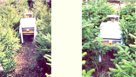
6.4.2 Quality of weedingFig. 6.6 shows the ACW at work in two different stands. As can be seen the space for the ACW in the row intervals is limited when the tree height exceeds 1.5 m. This is especially the case with the Normann fir, which due to a slow starting phase becomes very wide.
Fig. 6.6. The ACW at work in Norway Spruce (height 141 cm and width 92 cm), (left) and Normann fir (height 160 cm, width 142 cm), (right). All the plantation tests were done with the cutter positioning system in passive mode. The cutter followed the surface of the ground very neatly and the movements of the cutter around the trees created an approximately 35 cm band of cut weed plants on each side of the rows. Only in a very few cases the force of the spring was not sufficient to press the cutter below the lowest branches of the trees. In these cases the lowest branches were cut if not too thick – see fig. 6.7.
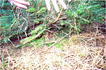
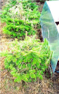
Fig. 6.7. Some low-sitting branches of a Normann fir has been cut off. In most Christmas tree plantations the pruning of the lower branches has been carried out already when the trees are about 1 meter high. The lower branches will therefore not cause any problems regarding this method of weeding. The weed plants were cut up to 1-2 cm from the stem of the trees, however as the weed standing close to the stem had grown up within the branches of the tree, it stuck to the tree even after the ACW had passed – see Fig. 6.8. This might have led to the impression of an unsuccessful weeding, however, when pulling these plants, it appeared that they actually had been cut, but still were stuck in the tree. – Within pruned trees and with regular mechanical weeding this phenomenon will not occur as the weeds never will reach such heights.
Fig. 6.8. Long weed plants that had grown up through the trees were held back by the branches although they were cut near the ground. This problem would not occur if weeding was done regularly. It was expected that cutting of heavy weeds like the mugwort with a stem thickness of 1.5 cm would be difficult with the knife used for the cutter. However, this turned out not to be the case. But the knives, which were made from polypropylene, did not last long, especially because of contact with stones. It was therefore necessary to replace them a couple of times during the test. This problem is however easily solved with use of knives made from a stronger material. The weeding performed with the passive cutter in the test plots was thus satisfactory, but in connection with mechanical weeding in new-planted and 1- 2-years-old trees it will be necessary to use the active cutter control unit (fig. 5.3). 6.4.3 Damages to treesNo considerable tree damage was observed, neither at the trunks or the branches where the machine had touched. However, with 4-5 weeding operations per season, wounding of the stems by the passive cutter cover may occur. Faint wounding of the bark at the base of the stem is, however, not very harmful and can even sometimes have a positive growth inhibiting effect on the leader shoot, when the tree is more than 1 meter high. Should such a wounding appear to be a problem it is possible to equip the cutter with a soft protection shield, which can rotate when it comes into contact with the trunk. The ACW was shielded by aluminium screens, partly to protect the machine and partly to avoid damage to the trees. It worked well during the test period, but should preferably be made more robust with a surface of synthetic material to reduce friction during work in the plantation.
|