Model assessment of reductive dechlorination as a remediation technology for contaminant sources in fractured clay: Modeling tool
2 Modeling approach
- 2.1 Conceptual model
- 2.2 Description of processes - Use of “sub-models”
- 2.3 Modeling tool – Comsol Multiphysics
2.1 Conceptual model
The contamination source is present in the upper clay system and contaminant is transported downwards to the underlying high permeability aquifer by advection through the vertical fractures and/or diffusion within the clay matrix. Contaminant transport in the underlying high permeability aquifer is controlled by advection in the horizontal direction. The conceptual model divides the problem into these two different blocks (Figure 2.1):
- A clay layer where the source is located
- A sand aquifer where a contaminant plume may form
This conceptual model reflects well the situations observed in different field sites in Denmark [Miljøstyrelsen, 2008]
Figure 2.1 – Global conceptual model, Ji is the water flux and Ci is the contaminant concentration
In this report, the modeling focuses on transport in the saturated zone only and considers TCE and its daughter products in the dissolved phase. The project focuses on the late time scenario, long after contamination has occurred, so it can be assumed that TCE has dissolved and diffused into the matrix and is no longer present in the residual phase. This assumption reflects the purpose of the project, which focuses on the remediation phase and disregards the contamination phase. In this project, the history of the spill is unknown and the starting point is the actual distribution of the contaminant.
2.1.1 Different fracture network scenarios – different conceptual models
The model will focus on the vertical fracture network, as it is assumed to control the contaminant flux to the underlying aquifer. The advective transport of contaminant in the clay system is neglected. However, diffusive transport is assumed to occur in all directions. Different scenarios for the clay matrix system are considered, depending on the nature of the vertical fracture network (Figure 2.2):
- Vertical fractures all along the clay layer to the high permeability layer
- Vertical fractures stop before reaching the high permeability layer
- No vertical fracture
This fracture distribution is very dependent on the thickness of the clay layer, as vertical fracturing decreases with increasing depth. More details on the geological characterization can be found in [Miljøstyrelsen, 2008]
Figure 2.2 - Conceptual models for the clay matrix system
In model (1), contaminant can be transported to the underlying layer by advection through fractures and diffusion through the bottom of the clay matrix. The contribution of these two processes to the total contaminant flux to the sand layer will be assessed in Appendix F. In models (2) and (3) the contaminant moves only by diffusive transport through the bottom of the clay system. In this project advection in the clay matrix is neglected and contaminant is assumed to be transported by diffusion processes only. This assumption is valid for very low hydraulic conductivity values but could become irrelevant in cases where the clay till presents an important sand content.
2.1.2 Single fracture/matrix model and aquifer model
The processes controlling contaminant transport are very different in the clay system and in the underlying high permeability layer. Therefore two separate models will be used to simulate contaminant transport, one corresponding to each system, the output of the first model being used as input to the aquifer model.
Modeling approaches for fractured porous media are generally divided into two categories, discrete fracture models and continuum models [Berkowitz, 2002]. In this work we are using a discrete fracture approach. The numerical model consists of a 1D-single fracture coupled with an adjacent 2D porous matrix (see Section 5.1.1 for more details). The scenarios presented in the previous section will lead to different numerical models of the clay layer.
In the aquifer model, the high permeability layer is simulated by a 2D flow model coupled to a contaminant transport model based on the advection/dispersion equation. The aquifer is represented by a vertical cross section (see Section 5.3 for more details).
2.1.3 Expected outputs from the model
The behavior of the source and contaminant transport between the fracture and adjacent matrix are characterized with the clay layer model. Furthermore the effect of enhanced reductive dechlorination on source mass removal, contaminant flux reduction and time frame are assessed. Output from the clay layer is used as an input to an aquifer model, which is used to assess the impact of mixing on the contaminant concentration and flux at a defined point of compliance in the aquifer.
2.2 Description of processes - Use of “sub-models”
The numerical model aims at simulate both contaminant transport in the fracture/matrix system and contaminant biological degradation. These two phenomena are complex and each involves numerous processes. Transport in the fractured clay till is controlled by diffusion and sorption in the matrix and by advection and dispersion in the fracture, while TCE dechlorination requires anaerobic redox conditions, contact between the contaminant, specific degraders and an electron donor. These different processes are illustrated in Figure 2.3.
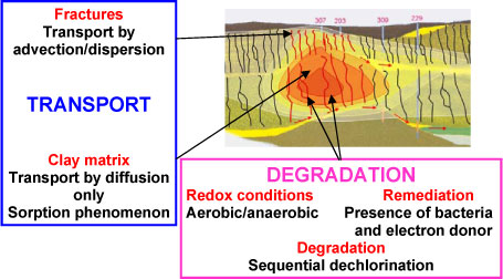
Figure 2.3 – Processes involved in the numerical model of the clay layer
In order to characterize the key processes controlling transport and degradation, it is necessary to separate the transport and degradation phenomena and set-up different models before coupling transport and degradation in one unique numerical model. Hence two “sub-models” have been set-up, one focusing on reductive dechlorination (Section 0), and the other on contaminant transport in clay (Section 1), before coupling the processes in a unique 2D-model. The modeling approach is illustrated in Figure 2.4.
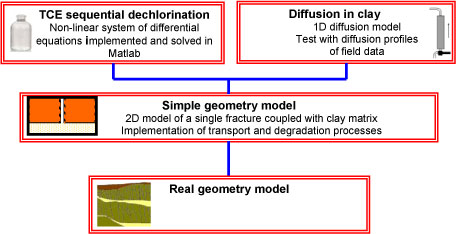
Figure 2.4 - Scheme of the modeling approach with use of "sub-models"
2.3 Modeling tool – Comsol Multiphysics
The sequential dechlorination model is developed using the mathematics package MATLAB. The clay matrix/fracture models are set up in Comsol Multiphysics, which is a commercial finite element code. This software is used to solve partial differential equations on defined domains in one, two or three dimensions.
Version 1.0 July 2009, © Danish Environmental Protection Agency