[Front page] [Contents] [Previous] [Next] |
Modern Windships; Phase 2
3. Rig DesignThe Difference between a Traditional Sailing Ship and a Modern WindShip
Traditional Sailing Ships
Former WindShip Projects
The Rig of the WindShip - Phase 1
Brainstorming and New Alternatives
Alternatives to Sailcloth
CFD Calculations
The WindShip rig is a relatively advanced construction, incorporating sandwich panels, hydraulic steering, etc which will be described in detail in the following sections.
The Difference between a Traditional Sailing Ship and a Modern WindShip
The rigs of traditional sailing ships were "children of their age". The design was based on the following principles:
- A traditional sailing ship reaches a certain speed determined by the speed and direction of the wind - no more, no less - as additional engine power is not used.
- The use of sailcloth requires a certain margin for the wind’s angle of incidence as the shape of the sail is generated by the wind pressure.
- The size of each single sail must be small enough to be handled by human power.
- The ship must be in yawing balance as the rudder is the only steering device.
- The rig design must be based on wood, iron and natural fibre ropes and sailcloth.
A modern WindShip differs from traditional ships in many areas.
As additional engine power will be used in most cases to reach a certain speed the angle of apparent wind will be shifted forward. This means that a rig for a WindShip must be better optimised for sailing upwind than the rig of a traditional sailing ship.
As fixed panels may be used in a WindShip instead of sailcloth a much wider range of angles of incidence can be utilised, see Figure 4 below.

Figure 4. Range of angle of incidence
Hydraulics and winches can substitute human power.
The ship does not have to be completely balanced (see chapter 8, section "Balancing the WindShip" below) as the propeller power can counterbalance the yawing moment. See also Figure 5 below.

Figure 5. Modern WindShip balanced with thrusters and rudder.
High tech materials as fibreglass, kevlar, carbon fibres, aluminium and high tensile steel may be used in a modern WindShip to make rig designs possible that were difficult to imagine just a few years ago.
Traditionally two types of rigs were commonly used: The square rig and the fore-and-aft rigs, see Figure 6.

Figure 6. Traditional sailing ships rig types.
The major and important difference between these two types is that the main sails of the square rig were symmetrical in relation to the mast and thus did not have a specific leading or trailing edge. The sails of the fore-and-aft rig however, had an asymmetrical sail profile with the greatest depth towards the leading edge. This profile was better suited for sailing upwind.
The square rig was the dominating rig for the large sailing ships. This type of rig presented the best solution of its age for a large rig that could be handled by human power, but from an aerodynamic point of view it was rather ineffective, especially when sailing upwind. The pressure difference between the leeward and windward sides of the sails was equalised through the horizontal slots between the individual sail, thus reducing the efficiency of the entire rig considerably. Apart from that the profile of the sails were far from optimal - completely flat at the upper edge and closing too much at the trailing end of the lower edge, see Figure 7.

Figure 7. Traditional square rig.
The maximum lift coefficient CL of a square rig was only 0.8 to 0.9.
The fore-and-aft rigs were dominated by the gaff rig. This type of rig used in smaller ships was considerably better from an aerodynamic point of view. A lift coefficient of 1.2 could be obtained.
Former WindShip Projects
Former attempts to design a rig for a windship can be divided into two major philosophies:
- Modern versions of the square or gaff rig, but with improvements in detail. Sail cloth and steel masts were normally used.
- More innovative solutions such as airfoils, foldable hard panels, rotors, etc.
The different former WindShip projects were discussed in detail in the report: Modern WindShips – phase 1, see Ref. 1. Some of the ideas are shown in Figure 8 & Figure 9 below.
Figure 8. Look here please.
Figure 8. Different rig types, reproduced from WindShip report phase 1. Originals by Peter Schenzle.
Figure 9. Look here please.
Figure 9. Coefficients for different rig types. Reproduced from WindShip report phase 1. Originals by Peter Schenzle.
The Rig of the WindShip - Phase 1
When starting the design work for a modern WindShip rig the following requirements were formulated:
| Must be handled automatically without requiring more crew. | |
| Must not interfere with the cargo handling. | |
| Must not jeopardise the safety of the vessel. | |
| Must be steady and reliable with a minimum of maintenance. | |
| Must be suitable for navigation upwind as the power from the propellers will shift the apparent wind forward. | |
| The air draught of the rig above a reasonable ballast water line must not be more than 60 m for passage of bridges. | |
| Must be reasonably easy to retrofit on existing ships. |
The rig system chosen in Phase 1 is shown in Figure 10 below.
Figure 10. Look here please.
Figure 10. The rig type chosen in phase 1 of the WindShip project.
The ship was equipped with a modern incarnation of the so-called "lugger" rig, having a certain resemblance to the rigs used in the traditional Chinese junks. Six self-staying pole masts were fitted in port side of the vessel for the sake of load handling and aerodynamics. Each mast was carrying a hoistable crane-type arm reaching to the ships centre line. A sail of approximately 1650 square metres was stretched between this arm and a boom positioned at the deck level.
This rig had many advantages but also a few drawbacks. One of the problems was stretching the lugger sail in an efficient way. Another problem was the wind resistance of the round pole mast when the sails were reefed. To overcome these problems it became clear that the steel mast should be an active part of the sailplane.
Brainstorming and New Alternatives
One of the first ideas that came up in the WindShip project was an U-shaped steel mast carrying a rather traditional sail on the trailing edge, see figure Figure 11.
Figure 11. Look here please
Figure 11. Brain storming, first idea.
The sail was equipped with shaped full-length battens. In the forward 1/3 of the batten length the sailcloth was double. Additional softer battens were fitted on both sides so that the 3 battens constituted a 3-fork. Air bags were fitted between the battens giving the total sail a very smooth and aerodynamic shape when the windward airbag was inflated, the leeward deflated.
One of the problems with this design was that the length of the battens was about 24 metres, making transportation of the sails rather difficult. The sails would have to be manufactured in horizontal panels and assembled on the location around the sail battens. If the width of the sail could be reduced to max 13.5 metres it would be possible to transport the sail complete, ready made from the manufacturer with boom, battens etc. in a 48 foot container.
Consequently, the next alternative was to use a broader symmetrical steel mast. A rig having a total area of 720 m2 and a max width of the sail of 13.5 m was developed. Of this area the mast alone made up for 300 m2, corresponding to 42% of the total area. As the mast was much wider than the previous design, air bags were no longer needed, simplifying the rig. The mast was self staying and rotating, see Figure 12 below.
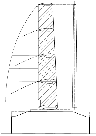
Figure 12. Brainstorming, second idea.
Modern sailcloth has one major problem when used in conjunction with modern WindShips, it deteriorates due to sun radiation. The estimated lifetime for a modern Wind Ship sail is max. two years. This means that 15 sets of sails will be needed during the ship’s lifetime of typically 30 years.
From modern windmills we know, that the estimated lifetime of the wings is at least 25 years. Switching from sailcloth to fibreglass panels might therefore be economically beneficial in the end.
In order to obtain the highest possible efficiency of a rig the profile must be asymmetrical. This requirement is automatically met with a traditional sail, but if asymmetrical fibreglass panels were used a system for shifting the profile from one side to the other had to be invented.
One of the ideas was to make a wing sail with a well-known airfoil profile. NACA 63-412 was chosen. The profile was cut in 3 vertical pieces; an asymmetrical trailing edge of around 61% of the chord length, a symmetrical centre part of 14% and an asymmetrical leading edge of 25%. The asymmetrical trailing- and leading edges were divided into 4 horizontal sections. Each section was suspended in a vertical slewing bearing at the centre line of the section. See Figure 13 below.
Figure 13. Look here please
Figure 13. High lift wing mast, stackable single profile.
By turning the 4 sections 180° around a horizontal axis the asymmetric profile was shifted from one side to the other. In order to reduce the area in severe wind conditions the bearings were fitted on vertical tracks from the bottom of the central mast to the top. Reefing could be done by turning one or more sections to a horizontal position, stack them on the deck and lower the remaining sections to the top of the stack.
CFD Calculations
In order to study the efficiency of an airfoil compared to a traditional sail, CFD (Computational Fluid Dynamics) calculations of three alternatives were performed at the Danish Maritime Institute (DMI/SL), see Ref. 3. The first alternative was to combine the broad steel mast and the 13.5 m wide sail. The other two alternatives were the NACA 63-412 wing mast profile and a slightly modified profile with a little more depth, see Figure 14.
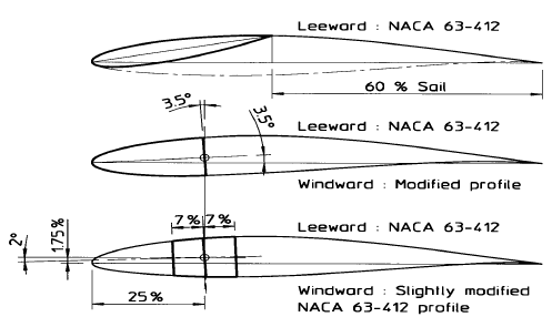
Figure 14. The three types of profiles used for CFD calculations.
The calculations were conducted at an angle of attack (a ) of 1°, 5° and 9°. The mast and sail combination proved to be the best with a lift coefficient CL of 1.4 at an angle of incidence of 9°. The airfoil had a max. CL of about 1.15, calculated at the same angle. However, in both cases the curve of the lift coefficient had not reached its maximum at 9°, so higher values at higher angles of incidence must be expected. Pressure distributions can be seen in Figure 15 to Figure 17, below.
Figure 15. Profile 1, pressure distribution at a =9°.

Figure 16. Profile 2, pressure distribution at a =9°.
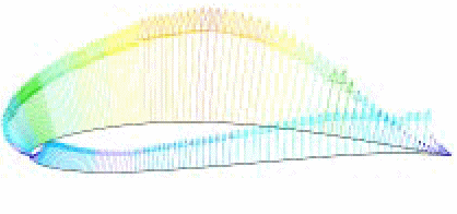
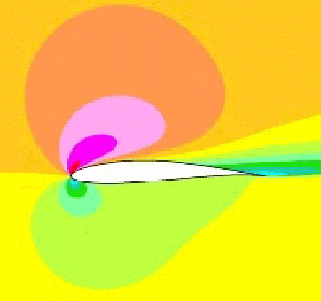
Figure 17. Profile 3, pressure distribution at a =9°.
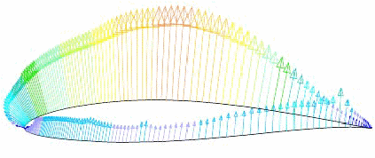

Extrapolating the obtained CL values of the combined steel mast/sail combination from a = 9° to a = 13° we get a CL of approximately 1.7. This corresponds well to the measurements performed later, see Ref. 4 and chapter 4 in this report.
The main reason for the difference in lift between the profiles was the different profile depths (camber). The depth of the mast / sail combination was about 12% of the chord length while the depth of the airfoil was only about 7%. The airfoil was designed for aeroplanes and not for WindShips.
An aircraft airfoil will at typical aircraft cruising speed produce more than sufficient lift. The task for an aircraft engineer is thus to develop an airfoil that gives minimum drag at low angles of attack. It is only during the start and landing phases that an aircraft needs to utilise the maximum lift coefficient.
For a sailing ship this is not the case. It is only in very high winds that it is necessary to reduce the available lift. Typically, at the WindShip’s cruising speed the task is to achieve the highest possible lift. A high-lift profile with more depth was therefore developed.
[Front page] [Contents] [Previous] [Next] [Top] |