[Front page] [Contents] [Previous] [Next] |
Modern Windships; Phase 2
5. Detailed Rig Design
Safety and Reliability
Behaviour of the Wing Mast in the Survival Mode
Turning of the Entire Mast
Turning of the Flaps.
Alternative I
Alternative II
Alternative III
Alternative IV – The Final Choice
Turning of the Four Horizontal Shafts
Fixing the Rotating Sections in a Vertical Position
Fixing the Flap to the Slat in the Folded-Up Position
Fastening of the Slats
High Lift Profile, Choice of Materials
Material Choice for the High Lift Profiles, Conclusion
Material Choice for the Mast
Material Choice for the Mast, Conclusion
Material Properties
Steel Material
Fibre Composite Properties
Core Material Properties
Structural Putty/Glue
In the following section detailed design of the mast will be described. Only the more complicated items were considered.
Safety and Reliability
The basic requirements to the rig with regards to safety and reliability were as follows:
- Any defect or malfunction must never jeopardise the safety of the vessel or the crew.
- Any maintenance work or inspection of hydraulics or equipment must be done from a safe working position.
- In the "survival mode" the mast must be able to withstand the worst possible wind conditions.
- The mast must not under any circumstances generate forces or heeling moments that are dangerous for the stability of the vessel or will jeopardise the manoeuvring possibilities.
- The mast must be flexible and be able to give away and relieve the wind pressure in case of sudden strong gusts.
To fulfil these requirements the following design characteristics were incorporated:
- The aft flaps were hinged at their leading edges and controlled by a hydraulic turning mechanism, designed to let the flaps give way and relieve the wind pressure at wind speeds exceeding 20 m/s. The ability to automatically reduce the lift in a smooth and non dramatic way is one of the clear benefits of the wing mast, compared with the sail mast where the sail will start to flatter.
- The mast could be reefed by folding one or more of the flaps up against the central mast. The "closed" mast was still an airfoil with a reasonable lift coefficient and with a very little drag. See Figure 24 below.
- The entire most would turn itself into the wind eye like a flag at wind speeds exceeding 25 m/s. In this "survival mode" the wind resistance from the mast will be very small because of the aerodynamic shape and the small projected area.
The different turning mechanisms are described in detail in the following sections.
Figure 24. Wing mast folded together.
Behaviour of the Wing Mast in the Survival Mode
A wing mast that is turned into the wind eye to survive strong winds has advantages but also some drawbacks compared with a sail mast.
The wing will remain steady because of the hard panels whereas the sail will start flapping strongly. On the other hand, if the direction of the wind starts changing quickly the sail will be flapping from side to side but without generating a lift.
The wing mast may start oscillating from side to side as lift is generated in alternating directions. To avoid this, it may be necessary to incorporate airbrakes in the upper part of the mast to reduce the lift generated. Small flaps that are extended perpendicular from the mast in the forward part would act as brakes. Airbrakes are well known from aeroplanes where they are used to reduce the lift of the wings once the plane has set its wheels on the ground.
If airbrakes are necessary at all is difficult to determine from wind tunnel test. If or when a large-scale test mast is built, the necessity of the brakes should be tested.
Turning of the Entire Mast
The entire mast is fitted on a slewing bearing on top of the weather deck. The inside of the bearing is fitted with a gear rim enabling the mast to be turned by two slow-turning hydraulic drives.
Alternatively, the mast could be suspended at the weather deck and the tank top in simple slide bearings but this arrangement would be more expensive, decrease the loading capacity and increase the weight.
The wind tunnel tests were conducted with vertical masts turning around a vertical axis positioned at the quarter length of the cord from the leading edge.
As mentioned, the mast should position itself in the wind eye like a flag in case of extremely strong wind or hydraulic or electrical failure. Thus the aerodynamic centre of the mast must be aft of the turning centre of the slewing bearing, even with the flaps reefed against the central mast.
Assuming that the aerodynamic centre is positioned on the quarter length of the cord of the reefed mast it was necessary to tilt the mast 4� aftwards and place the central steel mast at the aft end of the slewing bearing.
A slewing bearing with a raceway diameter of about 6 m would be sufficient to take-up the loads from the mast. However, a raceway diameter of 7.4 m has been chosen because of the following reasons:
- Large safety factor
- The larger diameter of the gear rim would lower the tooth pressure so that only 2 slow turning drives were necessary to turn the mast. (A raceway of 6 meters would require 3 motors.)
- If a raceway of 6 meters was chosen the mast would have to be fitted 6� aftwards instead of only 4� to position the aerodynamic centre of the mast aft of the turning centre.
The two slow turning hydraulic motors are bypassed by pressure relieve valves so that the entire mast will turn into the winds eye at a certain well-defined moment.
In order to relieve the gear wheels and the gear rim when the mast is not turning it would be advisable to fit a braking system e.g. a disc brace. This braking system should be designed not to prevent the mast from turning in case of a strong wind gust.
The mast has two working positions – open and closed. The largest turning moment of the motors is required when the flaps are open.
From the wind tunnel tests of a single wing mast the forces in the mast foot were available as coefficients (see Ref. 4).
| CL = Lift coefficient. | |
| CD = Drag coefficient. | |
| CN = Yawning moment around a vertical axis positioned on the quarter length of the cord. |
Multiplying these coefficients by the dynamic pressure:
| , where: |
v = the wind speed and r = the density of the air � 1.25 [kg/m3] and the relevant area will give the forces in N.
The forces in the slewing bearing were calculated using an Excel spread sheet. See Figure 25.
Figure 25. Mast foot calculation.
FN is the vertical force from the mast without acceleration allowance.
The friction coefficient of the slewing bearing is � = 0.001.
The result of the calculation shows that two slow turning drives, each with a turning moment of 1.1� 10.5 Nm, are necessary if the diameter at the gear rim is 7.4 m and the diameter of the gear wheel of each drive is 0.5 m. (Slow turning drivers, like the transmission-less H�gglund Viking 84-38000, are suitable for this purpose.)
Note that a wind speed of 25 m/s and a lift coefficient of 3.1 is used in the calculations although the flaps starts to give way for the wind pressure already at 20 m/s.
Turning of the Flaps.
Apart from the safety benefits turning and controlling the flaps have other advantages:
- The profile depth of the mast could be trimmed flatter when sailing upwind than when reaching and running. Especially, when sailing upwind it is beneficial to use a deep profile at the foremost mast and gradually flatter profiles for the aft masts.
- A certain twist could be established taking the difference in the direction of the apparent wind over the height of the mast into account.
The turning centre of the flaps had to be positioned close to the leading edge of the flaps as the air slot between the flap and the asymmetrical trailing edge of the central mast was to remain constant while turning the flap.
The high lift coefficient of the flap combined with the forward turning centre resulted in a large turning moment. The moment is calculated in Appendix 8. However, the best way to find the required moment would have been to measure it in the wind tunnel. We believe that the calculated moment is on the conservative side resulting in turning mechanisms that is too powerful.
As the flaps should automatically give way and relieve the wind pressure at a certain well-defined wind limit, a turning mechanism with a constant turning moment was desirable. Several alternatives were investigated all concentrating on creating a hydraulic constant-moment turning mechanism by-passed by a pressure relief valve.
The first suggestion was to use a modified rotary vane steering gear, like the gears typically used for turning the rudders on ships, see Figure 26.
Figure 26. Rotary vane engine flap turning mechanism.
A constant release moment was easy to establish simply by by-passing the hydraulics by a pressure relief valve.
Normally this type of gear has two (or three) internal blades to increase the turning moment, but as this gear should be able to turn the flap 200�, only one blade was possible. Consulting the company "Ulstein Tenfjord" (see Ref. 44) indicated that modification of a standard unit was possible.
The advantage of using a rotary vane gear was the well-proven high reliability, but the drawback was the high weight of about 6 tonnes per unit and it’s relatively high price. Moreover, the gear was positioned outside the mast so that maintenance and inspection was not as easy as desirable.
The conclusion was to investigate other alternatives although we still believe that a rotary vane gear custom-designed for this special purpose including all bearings for the flap would be a good, simple and very reliable solution.
The next alternative was to turn the flaps by means of large gear rims fitted at the top and bottom of the flaps.
The rims should be turned by gear wheels fitted on a common vertical shaft inside the asymmetrical trailing edge of the central mast. A slow turning hydraulic drive turned the shaft. See Figure 27.
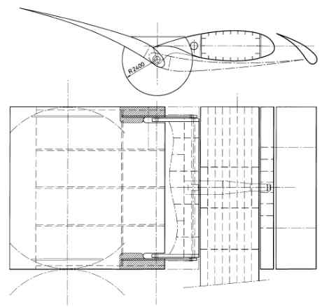
Figure 27. Gear rim flap turning mechanism.
In order to reduce the tooth pressure the radius of the gear rim should be as large as possible was necessary. (2.4 m was the maximum.)
- When turning the 4 flap-sections around the horizontal shafts the flaps describes 4 circles on top of each other when looking from the front of the mast.
- Despite the large diameter of the gear rims the tooth pressure is still very high. This could course unacceptable wear and tear as effective lubrication was difficult to establish.
As the gear rims with their large diameters should remain inside the circles they have to be positioned about 500 mm from the top and the bottom of the flap. This will complicate the design of the asymmetrical trailing edges of the central mast.
The flaps could also be turned by a hydraulic cylinder and link mechanism, see Figure 28.
Figure 28. Flap turning through link mechanism.
The disadvantage of this solution was that the turning moment was not constant, so it was difficult to create the constant release moment required for safety reasons.
Some kind of electronics would have to be incorporated to control the relief valve.
Alternative IV – The Final Choice
The final choice was to create a constant moment by a standard hydraulic cylinder acting on the flap via a girth around a disc integrated in the flap, see Figure 29
Figure 29. Hydraulic flap mechanism.
The maximum force in the girth was about 30 tonnes. A girth made of high-tech materials with a width of 300 mm and a thickness of 10 mm, was sufficient. (A girth called "Twin-Path" by Slingmax, see Ref. 46 could be used. The girth is slightly flexible, which will reduce the stresses in the structure in case of sudden gusts.
Apart from the flexibility a permanent elongation of the girth of about 2% must be expected over time. To control this flexibility and to avoid uncontrolled swinging of the flap a spring-loaded counter girth was fitted. The hydraulic cylinder should have a safe working load of 60 t. The cylinder and the rollers etc. were fitted inside the ø800 mm hollow shaft for easy access, see Figure 29 above.
The horizontal shaft consists of 2 parts joined together around a gear wheel used for turning the shaft. In both ends the shaft was suspended in "Thordon XL"-bearings (see Ref. 40) - a relatively cheap nylon material that absorbs shocks and does not need lubrication.
The flaps were suspended in "Thordon"-bearings like the horizontal shafts.
A hollow stainless steel shaft running inside a filament wound fibreglass tube was fitted inside the flaps from top to bottom, see Appendix 1.
The fibreglass tube was permanently bonded inside the flaps, whereas the steel pipe was exchangeable and fastened only in one end of the fibreglass tube. The outside diameter of the steel pipe was constant, but the wall thickness was increased in way of the bearings. The advantages of this system were multiple:
| A direct, stiff load path was created from the flap turning disc where the girth load is applied to the flap bearings. | |
| No fastening of metal structures inside the composite flap. Typically such fastenings are bolted, and inspection and spanning would be difficult. | |
| The shaft was easy to replace. |
The drawback of course is the weight. In the finite element analysis (see section "7. Strength Calculations using FEM" on page *) the steel shaft was not included, as it did not prove necessary for the overall strength of the flap. A lighter solution using locally fastened bearings should be investigated in a future project.
Turning of the Four Horizontal Shafts
As the horizontal shafts are positioned in the centre of each rotating section the moment required to turn the shafts is relatively small. A simple mechanism consisting of a gear rim around the shaft and a vertical toothed bar activated by a standard hydraulic cylinder was chosen. See Appendix 1. Drawings and Figure 30 below.
Figure 30. Rotating the high lift wing profiles.
Fixing the Rotating Sections in a Vertical Position
In order to relieve the turning mechanism for the horizontal shafts hydraulic cylinders are fitted in the aft part of the central mast to lock the trailing edge. Two cylinders are fitted each moving two synchronised locking pins. See Appendix 1. Drawings.
Fixing the Flap to the Slat in the Folded-Up Position
When the flaps are folded to the mast they must be locked. For this purpose an automatic locking device based on a spring-mounted fork fitted on the slat has been developed. See Appendix 1. Drawings.
The locking mechanism consists of a tong that turns around a fixed point. The tong is loaded by a spring mounted to hold the tong in open or closed position. When the wing is being folded together, the wing tip will touch the tong and force it to turn and eventually lock the tip.
To ensure that the tong is in the right position, capable of catching the approaching tip, a lace that will force the tong into the receiving position is fitted.
Fastening of the Slats
Both the asymmetrical leading edges of the centre mast and the slats are made of fibreglass sandwich.
The leading edge is bolted to a flange on the horizontal shaft. The slat is fitted to the leading edge by 3 horizontal streamline-shaped "bridges" (NACA-profiles). The upper and lover bridges are relatively thin profiles made of fibreglass on a foam core. The middle bridge is a little thicker and contains a fibreglass protruded hollow tube, glued into the core material, to give room for the hydraulic cylinder manoeuvring the flaps.
Figure 31 below shows the different fibreglass panels.
Figure 31: look here please
Figure 31. Fibre-glass panels
High Lift Profile, Choice of Materials
A short background on steel, aluminium, composite materials and sandwich constriction can be found in Appendix 3.
Material Choice for the High Lift Profiles, Conclusion
The high lift profiles are to be built of composite materials. They are described in more detail below.
Outer Shell
The outer shell of the high lift profile is a fibreglass sandwich construction. Face sheets of 2 mm quasi-isotropic polyester/fibreglass material were joined with a 30 mm Divinycell H80 core.
Internal Structure
The structure inside the high lift profiles is essentially a stiffened shell structure. Since the outer shells were sandwich panels, having a higher stiffness than single skin fibreglass panels, the distance between the internal stiffeners could be rather large. This reduced the overall weight of the structure. The internal stiffeners were of sandwich construction, using balsa core material where necessary instead of foam, to better resist buckling.
Aft End
The aft end of the high lift profile is narrow. A massive sandwich construction was therefore chosen in this region, using up to 90 mm thickness H60 Divinycell core and 2 mm face sheets.
External References
The construction of the flap, and other composite components, was made with active input from one of the leading composite part manufacturers in Denmark, LM Glasfiber, see Ref. 32. They have contributed with know-how, price estimates and design input during the process. However, all construction and strength calculations were carried out at Pelmatic Knud E Hansen. This collaboration resulted in a design that does not essentially deviate from the wind turbine blade construction principle, currently successfully being built by the thousands at LM Glasfiber.
The same evaluation criteria as for the high-lift profiles (HLP) were of course valid also for the mast. There were however a number of parameters that differed compared with the HLP.
The mast itself was of a simple symmetric shape. Basically the mast is a beam supported at one end, with a distributed wind load together with point loads at the HLP rotating points. A well-designed steel beam is weight efficient. A relatively large amount of fastenings were also necessary to incorporate the machinery and shafts necessary for rotating the profiles. Load introduction is typically much easier in steel structures than in composite alternatives.
Material Choice for the Mast, Conclusion
Aluminium was rejected due to fatigue, welding and corrosion reasons. Building with fibreglass was judged feasible, but was considered too complicated compared to high tensile steel. Carbon fibres would definitely reduce the weight, but at a significantly higher price. It was therefore decided to use high tensile steel.
The materials for the mast were chosen to get the best compromise between price and performance. The central mast was made of high tensile steel with a yield point of 420 N/mm2 up to the highest of the horizontal shafts. The top of the mast could be made of fibreglass sandwich to reduce the weight.
A central mast of fibreglass with carbon fibre reinforcements could probably perform better with lower weight and lower maintenance costs, but the price would be higher. In the future the possibility to use fibreglass should be investigated.
Material Properties
As described above the material chosen for the mast and its mechanical components was high tensile steel. For the wing panels a sandwich construction using polyester/fibreglass and foam/balsa core material was chosen.
The steel material properties are well defined, see Table 29. Elastic properties used:
E = 206.0 GPa
G = 80.4 GPa
Po = 0.3
The elastic properties of the fibreglass/polyester composite material was calculated using the normal "blending law" (see Ref. 30) using 50 weight per cent glass/polyester.
E = 13 GPa
G = 5 GPa
Po = 0.3
Maximum allowable stress was also taken from Ref. 30:
![]() Mpa
Mpa
Wrinkling Stress
A local failure phenomena corresponding to local buckling of the sandwich shell is when a sandwich laminate wrinkles in compression. A conservative estimation is Hoff’s formula:
| , Equation 4 |
where index f and c corresponds to the face and core respectively.
Here we get:
| MPa, well above the max. allowable by DNV. |
Most of the structure used 80 kg/m3 PVC foam. In lower stressed regions foam with lower density could be used, and vice versa. Data was taken from core material manufacturers data sheets, see Ref. 43.
EH80 = 80 MPa.
GH80 = 31 MPa.
Po = 0.32
Maximum allowable stresses, H80:
Shear strength: 1.0 MPa.
Tensile strength: 2.0 MPa.
Compressive strength: 1.2 MPa.
Joining the structural components in the sandwich structure, such as beams and panels, structural putty or glue is used. The strength of this material was assumed to be 4 MPa. No putty or glue was included in the finite element analysis described below.s
[Front page] [Contents] [Previous] [Next] [Top] |