Technical Documentation of PestSurf, a Model describing Fate and Transport of Pesticides in Surface Water for Danish Conditions
4 Result Presentation
- 4.1 Water balances
- 4.2 Solute balances
- 4.3 Graphical presentation of stream results
- 4.4 Sediment concentrations
Simulation result can be presented in several ways. A special spreadsheet has been prepared that displays the information in the result files in a graphical form and as tables. To the user it appears as if the results are displayed in Excell spreadsheets. In addition, the results can be viewed in MIKE View as ordinary MIKE 11-result files.
It should be noted that the first year of the simulation runs are given their "right" name. Therefore, the analysed years of the Odder Bæk scenario simulation are 1998-2005, while they are 1994-2001 for the Lillebæk scenario simulation.
4.1 Water balances
Due to the fact that limitations on the size of the water movement files limited the number of items that could be stored in each run, special runs were conducted with the specific aim of storing water balance informations. Tables with water balances are presented in Appendix E in the scenario report (Styczen et al., 2003b).
4.2 Solute balances
It is rather complicated to extract the values required for a mass balance as different processes are handled by different models. However, the simplest way to get an overview is the following:
For Wind drift and Dry deposition:
Open the file "Deposition_stream_spray.dfs0" under \TIME in the working directory. The file contains the amounts of solute arriving in the stream in mg/m2/sek, for each river section, over the eight scenario years.
To calculate the dosage entering the river by wind drift, take the concentration specified for the first half hour after spraying, and multiply with length and width of the stream, as well as the period (30 min). The ponds are only one segment, and the dimensions of the ponds are shown in Table 4.1. For the stream, the actual width of each segment of the stream at the time of spraying has to be found in the file "Input"DryDepositionCalculation.txt, as dx water for the respective segment and time.
The dry deposition is calculated in a similar fasion, except that the duration of spraying is either 7 or 21 days.
Table 4.1 Dimensions of streams and ponds in the scenario, for drift and deposition calculations.
Tabel 4.1 Dimensioner for vandløb og vandhuller i scenarierne, anvendt til drift og depositions-beregninger.Length, m Width, m Lillebæk pond 15.8 m 15.8 Odder Bæk pond 20 20 Lillebæk stream 1540 230 230 180 440 Odder Bæk stream 320 1610 1170 410 440 For other pathways to the stream, balances are available in the .tpf-file in the working directory.
Balances are stored at the end of the file, for each 360 days. The period can be changed in the .tsf-files in the template directory, but preferably not to less than 30 days =720 hours as the file becomes very large. The print in the tpf-file is shown in Figure 4.1.
The file contains the names of the species simulated, the period of the mass balance, and the transport from and to the different components. Overland to river and SZ (= saturated zone) to river, including direct grounDwater exchange and drain flow, are the two direct sources of solute from MIKE SHE to MIKE 11, in units of mg/m3 = g/l. "Sources to overland" is the total input of solute in mg to the sprayed area of the scenario. This area can be found in the spraying.psf-file at the top.
Additionally, balances can be retrieved for every 720 hours with the AD-retrieval programme of MIKE SHE (this frequency is also specified in the .tsf-files for the run).
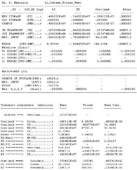
Figure 4.1 Solute balance of the tpf-file.
Figur 4.1 Stofbalance i tpf-filen.4.3 Graphical presentation of stream results
The programme "StreamConAna" was developed to facilitate creation of an overview for all the simulated data. An example of the graphics of the plot is shown in Figure 4.3.
The programme is started by opening the relevant excell template. These are found by pressing start, programs, DHI Software, Pesticides in Surface Water, Pesticide Tables and the relevant scenario. One template exists for each of the scenarios.
The spreadsheet is divided into several pages. The work starts by opening the setup-page, shown in Figure 4.2.
The MIKE 11 result file to be analysed has to be specified first. The river name should correspond to the selected template. The EUM type must be "concentration", and the species name is the name of the species specified in the user interface. If other simulation parameters are of interest, the names of these are written in the .AD11 file under \MIKE11 of the working directory. An example of such species could be:
[CompList]
DATA = 1,'Pesticide', 2, 0
DATA = 2,'Pesticide-Colloid', 2, 0
DATA = 3, 'Porewater conc.', 2, 0
DATA = 4, 'Adsorbed sediment', 2, 0
DATA = 5, 'Suspended matter', 2, 0
DATA = 6, 'Adsorbed macrophytes', 2, 0
DATA = 7, 'Sediment layer thickness', 6, 0
DATA = 8,'metabolite', 2, 0
DATA = 9,'metabolite-Colloid', 2, 0
DATA = 10, 'Porewater conc. metabolite', 2, 0
DATA = 11, 'Adsorbed sediment metabolite', 2, 0EndSect // CompList
Figure 4.2 Setup page of the result presentation programme.
Figur 4.2 Opsætningsside for resultatpræsentationsprogrammet.After these fields have been filled out, the file should be opened.
The locations (in m) specified in the spreadsheet are five locations for each stream scenario that represents selected points along the stream of particular interest. If "-1" is specified instead of a distance, the point is left out of the further analyses. The programme translates the distances specified to calculation cells and the corresponding time series in the result file (item in file). An item number must only occur once in the list.
Below the locations, a number of concentrations are specified (ng/l). These concentrations may be the detection level, or another minimum concentration of interest, and different toxicity indices of interest. When they have been specified, the button "build tables" should be activated.
On the following pages, the results are depicted for each concentration level specified.
The plot in the upper left corner show the length of the stream (y-axis), the time of simulation (x-axis) and the concentration of pesticide in the stream (colours). It thus integrates all the information generated by the simulation. For the stream plots, the variation along the stream is visible. For the ponds, only the upstream part of the graphics is of relevance. The ponds are allowed to spill over into a stream, and this part of the plot is not of relevance for the analysis.
In the lower left part of the graphics are shown time series for each of the locations specified on the setup page.
The plot in the upper right corner is an attempt to show how much of the stream is affected when a peak moves through the river system. When the concentration is higher than the detection level at the lower end of the depicted stream, the maximum concentration obtained during the last 24 hours is recorded for each calculation cell in the river. These values are depicted in the plot. It is thus possible to see how many events have been identified above a certain concentration and how long a stretch of the river has been affected by concentrations above a certain level during the event.
The plot at the lower right may either show the number of events with a max. concentration exceeding a certain value or the number of events with a duration longer than a certain value.
An event with respect to occurrence of pesticide or metabolite in the water body is defined as the period in which the concentration is above a specified value, e.g. a detection limit.
Below the graphics is a set of tables, one for each point specified along the stream (or pond), see Table 4.2. As the tables are produced in Excell, the results can be moved directly to reports, as required. The graphics can be exported as a bitmap by clicking on the right mouse-button when it is positioned on the graphics.
Figure 4.3 Example of graphics in the result presentation programme.
Figur 4.3 Eksempel på grafik i resultatpræsentationsprogrammet.Table 4.2 Example of a table generated by the result presentation programme.
Tabel 4.2 Eksempel på tabel genereret af resultatpræsentationsprogrammet.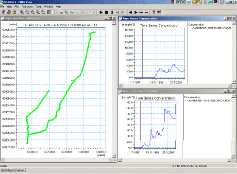
Figure 4.4 Example of test run on the Odder Bæk stream scenario, viewed in MIKE VIEW.
Figur 4.4 Eksempel på testsimulering af Odder Bæk-scenariet, set med MIKE VIEW.The results can also be viewed in MIKE VIEW, the standard viewer of MIKE 11. It allows analysis of the time series in greater detail, longitudinal plots of the stream and concentration profiles that can be depicted in time by a video. Figure 4.4 shows an example of a MIKE VIEW result-presentation.
4.4 Sediment concentrations
As the time series for sediment concentrations are similar to the concentrations in the stream, they can be interpreted with the aid of the same tools. This is done by substituting the name of the pesticide on the setup-page with the name "Adsorbed sediment" or "Porewater conc.", depending on which value is of interest.
Version 1.0 Maj 2004, © Danish Environmental Protection Agency