[Front page] [Contents] [Previous] [Next] |
Modern Windships; Phase 2
7. Strength Calculations using FEM
Scope of Work
Mast
Mast Foot
Flap
Buckling
Geometry used in FEM Calculations
Mast
Flap
Loads and Boundary Conditions
Mast
Flap
Results from FEM
Mast, Results
Mast Eigen-Frequency
Mast FE-model, Conclusion
Flap, Results
FE-Model of Flap Conclusion
Price and Weight Calculation
Summary and Conclusion regarding the Structural Design of the Wing mast
Loads
Weight
FEM Analysis
Computer Animation
In the following the strength calculations concerning the wing-mast will be documented. It is important to remember that this first design is preliminary, supplying data for further calculations on eigen-frequencies, weight distribution, centre of gravity etc. A more detailed analysis of individual details should be performed before the actual construction is undertaken. There is also a potential for design improvement regarding both cost and weight.
Scope of Work
The finite element method (FEM) is a method widely used for calculation of structural properties, stresses, strains and deformations of structures. In the WindShip project finite element analysis was used for assessing the strength of the steel mast and the aft sandwich flap. These two structures were chosen since they are the highest loaded large components. Detail solutions were not considered at this stage.
The goal of the finite element analysis was to evaluate the design proposals, and to give feedback to the design team regarding the feasibility of the design. As far as possible the analysis was to be performed in accordance with rule guidelines, such as DNV.
The entire mast was modelled to check overall deformations and stresses. The detail level of the model included stiffening beams, but not knees, local cut-outs etc.
The mast foot was included in the mast model. Post processing was performed simultaneously in both the mast and the mast foot. The detail level was the same as above.
The sandwich flap was modelled to check overall deformations and stresses. The detail level included the major panels with respective properties. The laminates were built up using equivalent properties as indicated above, not by stacking lamellas in the FE-program. Intralaminar shear stresses could thus not be checked. The geometrical modelling did not include local details such as fillet radii, fasteners etc.
Buckling was checked in the mast. Wrinkling stresses were checked in the flap.
Geometry used in FEM Calculations
Geometry was taken from available drawings, see Appendix 1. Details were not included.
The mast was modelled in accordance with drawings in Appendix 1. See also Figure 33.

Figure 33. Mast, general view.
The internal structure of the mast is best shown in Appendix 1, and in the result plots below.
The flap was modelled in accordance drawings in Appendix 1. In Figure 34 and Figure 35 below the complete flap is shown. Dark blue elements are sandwich, light blue solid laminate. The green aft end is a solid sandwich. The turning disc is modelled using stiffer sandwich elements.
Figure 34 Element plot no. 1 of flap with turning disc
Figure 35 Element plot no. 2 of flap with turning disc
The internal structure of the flap can be seen in Figure 36 below.
Figure 36 Composite flap without the outer sandwich elements.
In the figures above the entire flap can be seen. In the finite element solution only half of the model was used, together with symmetrical boundary conditions. This was done to reduce the computation time.
Loads and Boundary Conditions
Loads were applied according to the load chapter above. Only the "full sail condition" was checked. This condition was the most severe, as the mast is loaded sideways in its "weakest" direction. The exposed area was also significantly smaller in the reefed position, where the mast is turned against the wind.
As the "reefed condition" is determined from mast considerations, the maximum design moment is achieved at 25 m/s of wind in "full sail" condition. Individual sail pressures are determined from relieve valve settings in the hydraulic mechanism, thus 25 m/s as load criteria can be used.
On the mast the wind forces were applied as equivalent point loads on nodes. Masses were distributed inside the mast to simulate the internal mechanical equipment. Inertial loads were then added according to above. The bottom flange of the mast foot was locked for displacement in all directions around the perimeter. See Figure 37 and Figure 38 below.
Figure 37. The mast with boundary conditions and loads
Figure 38. Detail of the mast foot boundary condition.
On the flap an even pressure equivalent to the pressures calculated above was distributed. Two thirds of the load was applied as "suction" on the upper side, while one third was applied as "pressure" on the lower side. The pressures can be seen in below in Figure 39.
Figure 39 Wind pressure distributed on both sides of the composite flap.
A distributed pressure was also applied around the perimeter of the flange of the "disc". This simulated the pull of the hydraulic cylinder through the girth. See Figure 40 below.
Figure 40 The perimeter pressure load on the turning disc.
Inertia loads were also added according to above.
As explained above, and clearly visible in Figure 40 above, only half of the flap was modelled. Symmetric boundary conditions were therefore prescribed along the entire edge of the panel. The turning disc was locked for translation in the x-direction at the bottom of the disc perimeter. The axis seats were locked in all directions apart from rotating around the turning axis, the z-rotation, which was free. See Figure 41.
Figure 41 The flap boundary conditions. Note turning axis.
Results from FEM
When performing finite element analysis engineering judgement is essential, especially near sharp corners in the finite element model. Sharp corners will always result in high stresses, actually they are infinitely high, as the calculation domain, the so-called mesh, is gradually refined.
In the two models presented below some peak stress values above the max. stress limit can be found. They were located near sharp corners and could therefore safely be disregarded. The detail level of the modelling was not high enough to draw any conclusions regarding local fastenings etc. It was possible to determine if any larger components were under dimensioned, and the overall stress paths.
The results showed that the initial mast design met the criteria in most areas. High stresses were encountered in the lower part of the mast, just above the mast foot. A transverse structural element in the mast foot also showed high shear stresses.
None of the above issues were judged as indicative of a major design flaw, the high values of stress were local, and can be resolved by slight increases of local scantlings and careful detail design.
Below, in Figure 42 to Figure 48, results are visualised.
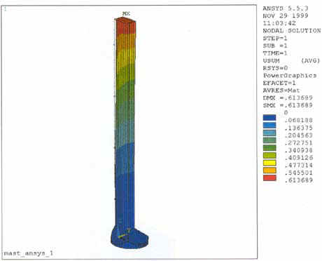
Figure 42 The overall deflection of the mast at full load, deflections in scale 1:1.
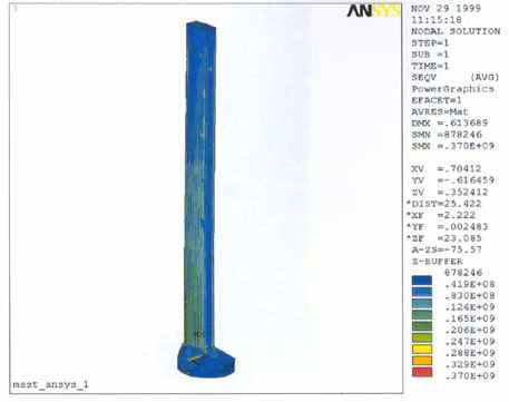
Figure 43. Von Mises effective stress in the mast.
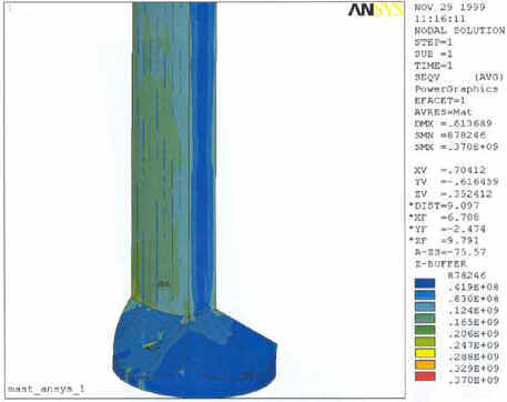
Figure 44. Von Mises effective stress, outside of the mast foot.
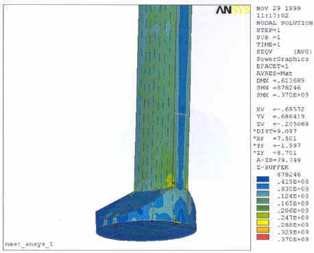
Figure 45 Von Mises effective stress, backside of mast foot.
Figure 46 Von Mises effective stress, inside mast foot.

Figure 47 Von Mises effective stress, inside mast foot.
Figure 48 Shear stress under mast in mast foot.
Buckling was also addressed. In the areas where the shells were relatively thick the design was stiffened sufficiently not to give way in buckling. At the top of the mast the outer shell thickness is 4 mm, and buckling could occur in highly stressed regions. This can easily be avoided by adding brackets, decreasing the stiffener distance etc.
The eigen-frequency of the mast was calculated using the finite element model. The lowest eigen-frequency proved to be 1.25 Hz. This was calculated without any aerodynamic damping included. However, the frequency is quite low, and may be a cause of concern. Further and more detailed analysis is recommended.
We conclude that the mast in general fulfils the stress requirements.
Due to the "backwards heeling" of the mast, and the aft position on the mast foot, the rear of the mast is quite heavily stressed. Local reinforcement may be needed to avoid fatigue cracking.
The inside of the mast foot is quite stressed in shear, as could be expected. Care should be taken to avoid cut-outs etc. under the mast in the structural elements. Extra buckling stiffening and local scantling increase to prevent fatigue cracks and other detail considerations should be undertaken in further design optimization.
Buckling checks showed that generally the mast internal stiffeners are placed sufficiently close together. Only at the mast top, where the sheet metal is 4 mm thick, there is a need to include some more buckling stiffening.
The low eigen-frequency might pose a problem, and result in fatigue cracking. Refined analysis including effects of aerodynamic damping is recommended.
The sandwich flap design proved to be within the DNV laminate stress criteria. The deflections were rather large, but the flexible construction was a conscious choice to reduce fatigue loads in the steel structure. Composite materials normally exhibit good fatigue properties.
Figure 49. The overall deformation of the flap at full load. Deformation scale 1:1.
Figure 50. Von Mises effective stress in the outer sandwich laminates, lower side.
Figure 51. Von Mises effective stress in the outer sandwich laminates, upper sides.
Figure 52. Von Mises effective stress in the solid laminates.
Figure 53. Core shear stress in the outer sandwich laminates.
Figure 54. Internal structure, von Mises effective stress.
Strains were also checked, and found to be within laminate limits.
By more detailed re-analysis it is anticipated that weight savings can be achieved, primarily by decreasing the scantlings towards the aft of the flap. Scantling reductions can also be made on the internal stiffening beams, high stresses occur only at the fastening of the axis. Buckling needs to be checked before this is undertaken.
FE-Model of Flap Conclusion
The flap scantlings generally proved adequate, or more than adequate, resulting in an unnecessarily heavy structure. A more refined analysis, with more varying dimensions could save weight and money before building the sandwich flap.
Price and Weight Calculation
Price and weight of the wing mast was of prime interest in the project. The weight is often relatively easy to determine as soon as the scantlings have been decided upon. It is often more difficult to estimate the price of a new construction, as a large part of the costs are developing costs. A relatively advanced computer control system must also be incorporated in the wing mast, but has not been looked upon at this stage.
For the wing mast "off the shelf" (commonly referred to as OTS-products) components were used as much as possible. This was done in order to reduce price and development time. The prices quoted below should therefore be judged as relatively realistic. There are of course some components that will need to be ordered specifically for the wing mast. Apart from the obvious: composite slats, flaps etc., the slewing bearing and raceway with a diameter of 7.4 m must be ordered specifically. Contact with SKF (see Ref. 36) has indicated that this causes no manufacturing problem, but the component is not in stock. All other components in the wing mast should basically be readily available from different manufacturers.
The composite part prices were determined in collaboration with LM Glasfiber, the world’s leading supplier of blades for wind turbines. The construction of the components also closely follow that already in existence at LM Glasfiber.
In Table 8 below the estimated prices and weights are summarised. A more detailed breakdown of the weights and costs can be found in Appendix 9. The alternatives given are for a wing mast built in Europe dimensioned for 25 m/s and 20 m/s. An alternative production price in a low-price area like the Far East is also given.
The following strategy was chosen for the calculation of the scantlings and the prices: Calculate the scantlings for a design wind speed of 25 m/s. Calculate the weight and price of the mast. Estimate the weight and price of the mast based on lower values of design wind speeds.
Mast Type |
Weight [Tonnes] |
Price [Million DKR] |
| Wind Speed 25 m/s. Built in Denmark. |
180 |
8.7 |
| Wind Speed 20 m/s. Built in Northern Europe. |
130 |
7.0 |
| Wind Speed 20 m/s. Built in Far East. |
130 |
4.0 |
Table 8. Wing mast estimated price and weight
Summary and Conclusion regarding the Structural Design of the Wing mast
The main components of the high lift profile were determined. The design incorporates a rotating symmetric high tensile steel mast, and asymmetric sandwich composite panels hinged on horizontal shafts through the steel mast.
Since the mast is relatively complicated, emphasis was made on making the structure as maintenance-free as possible. The mechanical design used components that should be easily available. Hydraulic components were used to operate all moving parts. All hydraulic equipment is accessible from inside the steel mast or the mast foot. To operate the flap a maintenance-free girth was used. No part of the mast protrudes below the weather deck, apart from structural reinforcements. It should therefore be possible to retrofit wing masts on existing ships.
Care was taken to use a design that did not push the design limit of the components. By this the solution is scalable, that is one could build both a bigger and a smaller wing mast by scaling the used components.
Loads were calculated using 25 m/s as design wind speed. This is the 10-minute average wind at 10 meters height above sea level.
Weight was calculated to approximately 180 tons per mast if dimensioned for 25 m/s of wind speed before reefing, 130 tons per mast at 20 m/s. This was considered too high. A weight reduction is high priority in the next phase of the project.
Finite element calculations were performed and showed that the general scantlings of the mast were adequate. Some local reinforcement may be necessary, but should be considered at a later stage. Eigen-frequency calculations gave rise to some questions that need to be considered in the future. The best way of increasing the frequency is to reduce weight aloft.
Computer animation was also performed during the modern WindShip project. The purpose was to show the mechanisms working, explaining the design result. The animation can be viewed separately, either on a VHS video cassette, or at lower resolution from a CD as a *.avi-file.
[Front page] [Contents] [Previous] [Next] [Top] |