[Front page] [Contents] [Previous] [Next] |
Modern Windships; Phase 2
8. Hull Design
Design of the Above-Water Hull
Tests Performed on the Hull
Wind Tunnel Tests of Above-Water Hull with Rig
Note on the Wind Tunnel Tests of Sails
The Hull Configuration Below the Waterline.
Rudder and Propulsion Systems
Propulsion Redundancy
Balancing the WindShip
WindShip Stability
Wind Tunnel Tests of Underwater Hull shapes
Tested Bow Types
The Four Tested Underwater Hull Configurations
Test Procedure
The Test Conclusions Summarised
Static Force Measurements of the Hull in Towing Tank
Model Description and Test Set-Up.
Test Conditions
Appendages
Summary and Conclusions from the Towing Tank Tests
PMM Tests
Speed, Drift and Heel
Speed, Drift, Rudder and Heel
Dynamic Course Stability
Design of the Above-Water Hull
Up to and including the weather deck the design of the WindShip looks like a traditional product tanker. The deckhouse is however a little unusual. In order to reduce the drag and prevent a blocking effect on the airflow form the aft-most sail, the deckhouse is a relatively low structure with a raised bridge fitted on two casings (for stairs, ventilation and exhaust). See Appendix 1. Drawings, and Figure 55 below.
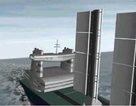
Figure 55. The deckhouse design.
Tests Performed on the Hull
The hull above and below the waterline was subject to several tests at DMI/SL, see Ref. 5, Ref. 6 and Ref. 7. The tests undertaken were:
| Wind tunnel tests with complete rig and above-water hull to determine the number and positioning of masts. Furthermore determination of aerodynamic coefficients. | |
| Underwater hull configurations, tests in wind tunnel of different underwater hull shapes to determine the best configuration. | |
| Towing tank tests of a 7 m long underwater hull model in order to find the hydrodynamic forces acting on the hull |
The tests are further described below.
Wind Tunnel Tests of Above-Water Hull with Rig
Wind tunnel tests of a complete above-water hull with multiple wing masts were conducted in an open boundary-layer tunnel at the Danish Maritime Institute with the hull and masts in scale 1:225. The tests and the results were described in detail in "Report No. 2: Ship Performance with Complete Rig", see Ref. 5. See also Figure 56 below.

Figure 56. The modern WindShip wind tunnel model in the seven mast configuration.
In contrast to the single wing mast as described earlier the flaps of the smaller wing masts were fixed and individually adjusted to a position for maximum lift. This means that the test results, when sailing upwind, were slightly conservative, as a flatter profile should have been used at these upwind courses.
The deck of the model consisted of a hole-board making it possible to test different positions of each wing mast both in longitudinal and transverse direction. Two basic configurations were tested: One configuration used 7-wing masts - 6 large masts and one smaller forward to allow space below the mast for an auxiliary bridge in the bow. The other combination had 6 identical wing masts with larger mutual spacing. The 7-wing mast configuration can be seen in Figure 56 above.
The results from the tests showed that the 7-wing mast configuration was slightly better than the 6-wing mast configuration, but that the difference was less than 10% at all tested wind angles. It was concluded that this small difference was not enough to pay for an additional mast. The 6-wing mast configuration was therefore chosen. The foremost mast is the most efficient as it has free wind. This mast should thus be of maximum size like the other masts. Another solution for the auxiliary bridge must be found.
One would also expect that the mast efficiency, especially when sailing upwind, could be improved by fitting the masts on transverse tracks making it possible to shift each individual mast from side to side. This was also tested using the hole board, but the increase in efficiency was only about 7%. The expenses and the difficulties with such a track system were considered to be economically non-profitable.
The final conclusion was to fit 6 equally spaced wing masts in the centre line of the ship with the first mast as far forward as possible. Probably it would be slightly better if the forward masts were positioned closer together than the aft masts, but to reduce the amount of tests this was not tested.
Bubble visualisation showed that large vortexes were created at the bow of the ship at upwind courses because of the sharp bulwark. A smooth forward canopy should be incorporated in the final WindShip design.
At the top of the mast (and less pronounced at the bottom) the pressure equalisation between the windward and the leeward sides created a large vortex resulting in an efficiency loss. The vortex was especially large, as the cord length was not tapered towards the top as a typical aeroplane wing. Incorporating winglets might increase the efficiency of the mast considerably, but this was not tested.
The wind tunnel tests with multiple masts also provided a series of non-dimensional aerodynamic coefficients for the rig. These coefficients were used in developing the velocity prediction programme (VPP). See further page *, section "9. Simulations".
Note on the Wind Tunnel Tests of Sails
It would not have been possible to use other methods than wind tunnel measurements to get the necessary data. Although further computational fluid dynamics (CFD) could have been used for parts of the tests, it is yet very difficult to get reliable results from CFD when it comes to high lift devices. This is due to the small scale boundary layer effects are hard to incorporate in the large-scale models necessary. Especially when testing an entire ship this becomes obvious.
The Hull Configuration Below the Waterline.
The loading capacity of 50.000 dwt. and the main dimensions of the hull were kept the same as the design criteria in the first report "Modern WindShips, Phase 1", see Ref. 1. This meant a design draught of 12 meters according to port restrictions and a breadth of 32.24 meters as per Panama Canal restrictions.
In order to achieve reasonable sailing ship characteristics it was decided to design the hull lines slimmer and to include a bottom rise, compared to a conventional vessel with the same dead-weight capacity. The resulting block coefficient was 10-12 % lesser than a conventional ship, which meant that the length had to be increased by 10-12 % if the same loading capacity should be achieved.
The resulting main particulars of the hull can be found in Table 9.
Length overall abt. |
220.00 m |
Length between perpendiculars |
210.00 m |
Breadth moulded |
32.24 m |
Depth to main deck moulded |
19.00 m |
Draught moulded to design draught |
12.00 m |
Draught moulded to freeboard draught |
13.40 m |
Displacement to design draught abt. |
61600 ton |
Displacement to freeboard draught abt |
70400 ton |
Block coefficient at design draught |
0.74 |
Table 9. Modern WindShip hull main particulars
Rudder and Propulsion Systems
To define the engine power requirements for speed and manoeuvring for a modern WindShip is a difficult balance between economy and safety. An oversized and too costly engine installation can spoil the overall economy, and a too small engine power can lead to accidents and in the worst case, loss of the vessel.
Earlier suggestions for wind powered vessels having the wind as the main propulsion system were characterised by their relatively low installed engine power. Critics of wind powered vessels have often claimed that these vessels with their large windage and small engines would not fit into the modern traffic pattern at sea. Especially in narrow and much trafficked areas and when entering and leaving ports they represent a potential risk not only for a wind powered vessels, but also for other vessels. Furthermore in heavy weather situations close to a lee shore, vessels with small engine power can easily be subject to dangerous situations.
Other criticism was pointed towards the general service reliability offered by a wind powered vessel, inherently showing varying voyage duration’s and consequently problems with realistic predictions of the arrival time. With these factors in mind the following criteria were established for the determination of the required engine power to be installed.
1. It should be possible to maintain sufficient and
well-defined average service speed either for:
- Wind Power without engine assistance.
- Wind Power + engine assistance.
- Engine Power without Wind Power.
- Convoy operation without Wind Power (Suez).
2. Sufficient propeller thrust to prevent drift in open sea
during severe weather conditions.
3. Sufficient transverse thrust to give a manoeuvrability
not less than a similar normal engine driven vessel.
To fulfil these requirements the following rudder- & propulsion system is proposed:
| Two 360 degrees rotating azimuth well mounted propellers at the stern for propulsion and balancing the ship during tacking under sail. | |
| One transverse thruster forward for steering of the bow in manoeuvring situations. | |
| One single spade rudder aft for general steering. |
In principle the vessel would have two independent main propulsion systems, the wing masts and the installed diesel machinery.
The "wind propulsion" is split up into 6 separate units (masts), giving a very high degree of redundancy.
The diesel machinery is divided into two separate units, each having their own propulsion unit. In case of a breakdown of one of the main engines, the other unit remains functional.
Steering can be done independently using the rudder, the azimuth propellers, or to a lesser degree the bow thruster and the sails.
The chosen system has the following advantages:
| With favourable wind speed and direction to obtain the ships service speed without engine assistance, the propellers are stopped or left to rotate freely, the rudder controlling the ship’s course. | |
| In low wind, sailing upwind or tacking some engine assistance may be required using one or two of the azimuth propellers, adjusted to a thrust angle to obtain the service speed and course balance of the ship. | |
| With full engine propulsion in calm or head wind the two azimuth propellers will propel and steer the ship. | |
| During manoeuvring the azimuth propellers aft and the transverse thruster forward can turn and steer the ship with high precision, allowing for a complete envelope of manoeuvres. |
Compared with a conventional full engine driven vessel, normally only having one engine and one rudder, a modern WindShip equipped with this engine- and propeller layout would have a superior level of safety and manoeuvrability. It could for example enter and leave ports without the assistance of tugs.
In a period where the safety at sea is in focus - especially with respect to tankers and bulk carriers, where too many total losses have been experienced over the last decade - the modern WindShip can contribute positively to address this problem.
One of the more complicated aspects when designing a sailing ship is the balancing of the aerodynamic and hydrodynamic forces. Ideally the longitudinal position of the force resultant from the sails should coincide with the force resultant from the underwater body longitudinal position. In general the position of the force resultant on a flat panel is approximately at Ľ of the chord from the leading edge. The centre of effort from the underwater body can thus be approximated at a quarter-length line from FP. The centre of effort from the six sails can roughly be estimated to the geometrical middle of the sail areas. All in all this results in a yawing moment, which must be compensated for by applying rudder angles. This way an equilibrium in yawing moments can be found, and the ship can sail at a straight course.
Without measurements it is difficult to determine these yawing moments, and much experience is needed to design a well-balanced sailing ship in such circumstances. In the modern WindShip project the necessary measurements were performed, the results were then incorporated in the Velocity Prediction Programme (VPP).
WindShip Stability
The stability conditions for a WindShip is of course of great importance. Besides the general stability requirements valid for all ships, the wind forces acting on the wing masts under severe weather situations constitutes a potential risk to the WindShip.
The general intact stability requirements valid for all ships, are fulfilled with excellent margin for the WindShip, both in loaded and ballast condition. See Table 10 below.
| Condition | Unit | Required | Loaded | Ballastet |
| Draught design | m | - | 12.00 | 6.80 |
| Displacement | ton | - | 61600 | 31600 |
| Metacentric height GM | m | 0.150 | 1.74 | 5.11 |
| Area under GZ-curve 0-30 deg. | m*rad | 0.055 | 0.31 | 0.75 |
| Area under GZ-curve 0-40 deg. | m*rad | 0.090 | 0.58 | 1.25 |
| Area under GZ-curve 30-40 deg. | m*rad | 0.030 | 0.27 | 0.49 |
| Maximum GZ-lever | m | >0,200 | 1.66 | 2.95 |
| Minimum angle at max. GZ-lever | deg | 30 | 42.9 | 43.6 |
Table 10. Intact stability analysis of the WindShip
The stability under wind pressure has been calculated according to: IMO resolution A.562(14): Recommendation on a severe wind and rolling criterion (Weather criterion) for the intact stability of passenger and cargo ships. According to this resolution the ship has to withstand the combined effect of beam wind and rolling as follows:
| The ship is subjected to a steady wind pressure acting perpendicular to the ship’s centre-line, resulting in a steady wind heeling lever. | |
| From the resultant angle of equilibrium, the ship is assumed to roll owing to wave action to an angle of roll to windward. Attention should be paid to the effect of steady wind so that the resultant angles of heel are not excessive. | |
| The ship is then subjected to a gust wind pressure which results in a gust wind heeling lever. | |
| Under these circumstances, area ‘B’ should be equal to or greater than area ‘A’. See Figure 57 below. |
Figure 57. Stability curves for the modern WindShip
In addition to the wind pressure requirement (504 N/m2) stipulated in the IMO resolution, the maximum allowable wind pressure acting on the total area of the wind masts was calculated. The maximum wind pressure would be the wind pressure where the ship will not exceed the rule limits for heel and moments. As it appears from Table 11 below, the vessel was able to withstand a wind pressure about twice the rule requirement.
| Condition | Unit | Required | Loaded | Ballastet |
| Steady wind pressure according to resolution | N/m^2 | 504 | 504 | 504 |
| Full windage area above the current waterline | m^2 | 7640 | 8750 | |
| Vertical lever to center of wind pressure | m | 29.8 | 29.0 | |
| Steady wind heeling angle | deg | 6.2 | 4.6 | |
| Steady gust wind heeling angle | deg | 8.5 | 6.6 | |
| Heeling angle where area 'B' => 'A' | deg | 27 | 34 | |
| Heeling angle when deckedge submerge | deg | 24 | 41 | |
| Max allowed steady wind pressure for fulfilling the criteria | N/m^2 | 504 | 1059 | 1118 |
Table 11. Results of intact stability analysis according to IMO res. A.562(14).
In addition to the intact stability investigations, the damage stability should also be investigated. As it was outside the limits of the present study to design the subdivision in the cargo- and engine compartments it was not possible to make a damage stability analysis. In a later design phase a complete analysis of the damage stability should be executed.
Wind Tunnel Tests of Underwater Hull shapes
Apart from the balance requirements described above, an important parameter in sailing ship design is the drift angle. The drift is a result of the large side-force generated by the sails, specially when sailing upwind. In order to determine the best possible underwater hull shape wind tunnel tests were performed.
Type A: An "Ice breaker" stem fitted with a bow fin with relatively high aspect ratio to produce transverse lift. A centre skeg is provided with sufficient room for installation of the transverse bow thruster. The centre skeg will also contribute to the generation of transverse lift and course stability. See Figure 58 below.
Figure 58. Type A bow type.
Type B: A more traditional vertical stem without bulb, but rather sharp to ensure that turbulent flow around the stem was minimized. See Figure 59 below.
Figure 59. Type B bow type.
The aft parts of the two hulls were identical. It is a rather traditional hull form of the pram type fitted with a centre skeg. The centre skeg will in traditional ships contain part of the engine-and propulsion plant. In the WindShip it will contain the equipment and pocket for the centreboard. See Figure 60 below.
Figure 60. Aft part of tested hull
The Four Tested Underwater Hull Configurations
Combining the two bow types described above with different fin and rudder arrangements a total of four underwater hull configurations were tested in the wind tunnel. The configurations can be seen in Figure 61 below.
Figure 61. The four tested underwater hull configurations.
Under Water Configuration 1:
Fore body type B, one single rudder aft, two centreboards below the hull.
Under Water Configuration 2:
Fore body type A, one fixed bow fin, one single rudder aft, one centreboards below the hull.
Under Water Configuration 3:
Fore body type A, one fixed bow fin, one single rudder aft, no centreboards below the hull.
Under Water Configuration 4:
Fore body type A, one fixed bow fin, two large twin rudders aft, one centreboard below the hull.
As wind tunnel tests are less expensive than towing tank tests, models of the under-water hull in scale 1:225 were tested in the same wind tunnel as the above described tests of the above-water hull with multiple masts. The tests and the results were described in detail in Ref. 6, "Report No. 3: Underwater Hull Configurations". It was decided to test the two types of bow combined with different lift producing fins and rudders to be able to select the optimum underwater configuration. A picture of one of the tested underwater bodies in the wind tunnel can be seen in Figure 62 below.
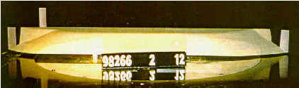
Figure 62. An underwater hull model in the wind tunnel (configuration no. 2).
The underwater part of the hulls was used to measure the static current loads and moments acting on the hull for drift angles 0° to 20° . The loads and moments were also measured for a drift angle of 90° .
The longitudinal (X) and transverse (Y) forces and the heeling (K) and the yaw (N) moment in non-dimensional form together with the centre of attack calculated from the N-moment and the Y-force were presented in Ref. 6.
The Test Conclusions Summarised
In general the measured differences between the four hull configurations were minor.
The point of attack of the current forces in the range 0° to 20° was shown to lie between amidships and 0.3 ´ Lpp forward of amidships for all configurations. The most stable configuration was no. 2, which gave values between 0.1 to 0.2 ´ Lpp forward of amidships in the whole range. Configuration no. 2 was thus chosen for further studies in the towing tank.
Static Force Measurements of the Hull in Towing Tank
To provide non-dimensional coefficients for the chosen hull, a 7.5 m long wooden model in scale 1:28.2 was manufactured and tested in the towing tank at the Danish Maritime Institute. The hull was suspended in a so-called "Planar Motion Mechanism" (PMM). Three different modes of propulsion were tested: zero thrust, 50% and 100% power. Four different speeds were also tested: 7, 11, 13 and 15 knots. The experiments covered a drift angle range from 0° to 20°, while the tested rudder/azimuth-thruster angles varied from 0° to 40°.
All the combinations of drift angles and speeds with corresponding propeller loading and rudder angles of 0° and 20° were then repeated with the model inclined 8°. The tests and the results were further described in "Report No. 4: Static Force Measurements on a Model of the Wind Ship", see Ref. 7.
Model Description and Test Set-Up.
The model ship hull structure was made of wood. The overall geometry was based on drawings and NAPA lines developed at Pelmatic Knud E. Hansen A/S.
The model scale was 1:28.22322. The model (No. 98267-10 (P 5107/A), condition 01) had the following dimensions, see Table 12:
DIMENSIONS |
Lpp [m] |
Bmld [m] |
T [m] |
Model scale |
7.441 |
1.142 |
0.425 |
Full scale |
210 |
32.24 |
12.00 |
Table 12. Model scale dimensions of the modern WindShip
The aft of the tested model can be seen in Figure 63 below.
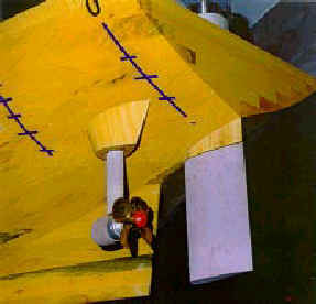
Figure 63. Photo of the aft of the model. Note the azimuth thruster and the relatively small propeller.
The test conditions were as listed in Table 13:
| Test Condition 01 | Model |
Ship |
Displaced volume |
2.672 m3 |
60065 m3 |
Draught Forward, TF |
0.425 m |
12.00 m |
Draught Aft, TA |
0.425 m |
12.00 m |
Nominal Speed |
1.452 m/s |
15.0 knots |
Table 13. Test condition 01.
The model was fitted with:
| Twin azimuth thruster units. | |
| One 0.0723m2 (57.6m2) centre-spade rudder. Span to chord ration = 9.6/6.0 | |
| One 0.0615m2 (49.0m2) centreboard below the keel at station 1.2 Span to chord ration = 10/4.9. | |
| One 0.0820m2 (65.3m2) bow fin. Mean span to chord ratio = 12.0/5.4. |
Propellers
The azimuth units were fitted with DMI stock propellers number 71087 mounted on the aft side of the units. The port propeller was left-handed and the starboard right-handed. The pitch ratio was adjusted to 0.845.
Test Matrixes
The test matrixes for the trials are covered in the following tables, see Table 14 and Table 15 below.
| Velocity | 7 knots |
11 knots |
13 knots |
15 knots |
||||
| Drift angle | -20° |
-16° |
-12° |
-8° |
-4° |
0° |
||
| Rudder angle | -40° |
-30° |
-20° |
-10° |
0° |
20° |
||
| Heel | 0° |
8° |
||||||
| Power | 0% thrust |
|||||||
Table 14. The test matrix for 0% thrust trials
| Velocity | 7 knots |
11 knots |
13 knots |
15 knots |
||||
| Drift angle | -20° |
-16° |
-12° |
-8° |
-4° |
0° |
||
| Rudder angle | -40° |
-30° |
-20° |
-10° |
0° |
20° |
||
| Heel | 0° |
8° |
||||||
| Power | 50% power |
100% power |
||||||
Table 15. The test matrix for 50% and 100% thrust trials.
Summary and Conclusions from the Towing Tank Tests
A large number of results were available from Ref. 7. The results are summarised below.
The specific test data was listed in Ref. 7. A large amount of data was recorded; some selected data in ship scale is presented in Table 16 to Table 18 below.
| Constant values: velocity=13kn, rudder angle=-10° , 50% power, heel = 0° | ||||
| Drift angle | 20° | 12° | 8° | 4° |
| Forward force | -857 kN | -753 kN | -647 kN | -694 kN |
| Turning moment | -372089 kNm | -159310 kNm | -66442 kNm | -9139 kNm |
Table 16. Note that the velocity and rudder angle were constant in this specific table.
| Constant values: drift angle=-16° , rudder angle=20° , 50%power, heel= 0° | ||||
| Ship velocity | 7 kn | 11 kn | 13 kn | 15 kn |
| Forward force | 137 kN | -335 kN | - 752 kN | -1193 kN |
| Turning moment | -156816 kNm | -365416 kNm | -521136 kNm | -712497 kNm |
Table 17. Note that the drift and rudder angle were constant in this specific table.
| Constant values: velocity = 13kn, drift angle = -20° , 50% power, heel=0° | ||||
| Rudder angle | 40° | 30° | 10° | 0° |
| Forward force | -1939 kN | -1571 kN | -857 kN | -635 kN |
| Turning moment | -182801 kNm | -237798 kNm | -372089 kNm | -449014 kNm |
Table 18. Note that the velocity and drift angle were constant in this specific table.
From Table 16 it is seen that the drift angle is a very significant factor for the turning moment but not so much for the forward force, when all other parameters are kept constant.
Table 17 shows the turning moment is much less influenced by the speed than the forward force is, when keeping all other parameters constant.
Table 18 states that changing the rudder angle changes the resistance and moment with a factor close to three in the total rudder working range.
Due to the complexity of the data interaction, together the varying wind, a Velocity Prediction Programme (VPP) was developed especially for the modern WindShip project. The program predicts the speed, the drift angle and the rudder angle for given wind direction, wind speed and propeller loading. The programme used input from the static PMM-test carried out at DMI and from the wind-tunnel measurements described in section "Wind Tunnel Tests of Above-Water Hull with Rig" on page * above.
Comparing the speed and drift results for 0° heel with the 8° heel results showed that the longitudinal tension force (X) versus the drift angle was not affected by the inclination of the vessel. The transverse forces versus the drift angle decreased by about 7% as a result of the 8° heel angle, while the yaw moment versus drift angle was increased by about 13%. I.e, transverse force decreased with heel, yaw moment increased with heel.
When comparing the drift and rudder results for 0° heel with the results for 8° heel the following could be concluded:
| The longitudinal force versus drift when the rudder angle equalled –20° (starboard rudder angle) was not affected by the inclination of the vessel. | |
| The transverse force versus the drift angle with a rudder angle at –20° and 8° heel corresponded to the results without heel angle. But since the (transverse force, drift angle) function was reduced by about 7% as a result of 8° heel angle (as observed above), it followed that the transverse force due to rudder action was increased by the same amount when the vessel was heeled 8° . | |
| The yaw moment as a function of drift angle, with the rudder angle at –20° together with 8° heel angle, was about 25% higher than the yaw moment at 0° heel. Since the yaw moment with zero rudder angle increased by about 13% when heeled (as observed above), it followed that the increase of yaw moment due to the rudder action in the heeled condition was of the same size. |
Pure yaw test. The stability criterion showed that the vessel in the present configuration was course stable at 15 knots with engine propulsion. It is realised that the vessel cannot maintain a speed of 15 knots running with the propeller alone, but a vessel’s course keeping ability is, in general, rather independent of its speed. The retraction of the centreboard will, however, affect the course keeping in a negative way, but with the twin azimuth units no problems were foreseen.
Regarding the bow fin it was assumed that this feature did not improve the course stability, when evaluating the solely engine powered ship. However, a design incorporating the bow fin seemed a feasible way to counterbalance the large side forces from the wing masts.
[Front page] [Contents] [Previous] [Next] [Top] |