[Front page] [Contents] [Previous] [Next] |
Environmental and technical characteristics of conductive adhesives versus soldering
8. Test of electrical conductive adhesives
8.1 Survey of electrical conductive adhesives tested
8.2 Survey of test
substrates
8.3 Survey of the
mounted components
8.3.1 Passive
components on each substrate variant
8.3.2 Active
components on each substrate variants
8.4 Survey of the
samples (adhesive/substrate)
8.5 Survey of the
mounting process
8.5.1 Stencil
printing of adhesives/solder paste
8.5.2 Dispensing
of adhesives
8.6 Component
mounting
8.7 Curing/soldering
8.8 Cleaning
8.9 Test plan
8.10 Description
of the tests
8.10.1 Adhesion
test
8.11 Current -
temperature
8.12 Discussion
8.13 Comments to
each electrical conductive adhesive varian
The present test is a quality assessment of 13 electrical conductive adhesives from ten different manufacturers. The variants include adhesives based on epoxy and silicone with silver or carbon particles. Further adhesives with silver on aluminium particles and silver on copper particles were included. The adhesives have been tested on four different substrates; ceramic and polyester substrates with silver conductors and FR-4 substrates with gold over nickel and tin lead conductors. The components attached to the substrates had silver palladium and tin-lead finish on the terminals.
The test programme included environmental testing of the component to substrate connection. A lead-free solder paste was tested as a reference.
The interconnection resistance was tested before and after all environmental exposures, and the shear strength was tested initially and after the final exposure.
8.1 Survey of electrical conductive adhesives tested
The tested electrical conductive adhesives are shown in table 8.1 (The information is from the manufacturer's datasheet).
| 6 electrical conductive adhesive variants, nos.1, 2, 3, 4, 5 and 6, are epoxy with silver particles, all 1-component except for variant no. 6 which is a 2-component adhesive. | |
| 1 variant, no. 7, is 'thermoplastic' 1-component electrical conductive adhesive with silver. | |
| 1 variant, no. 8, is 'thermoset' 1-component electrical conductive adhesive with silver. | |
| 3 electrical conductive adhesive variants, nos. 9, 10, and 11, are silicone, variant no. 9 is a 2-component adhesive with silver, variant no.10 is a 2-component adhesive with silver-plated aluminium particles and variant no. 11 is a 1-component adhesive with silver-plated copper particles. | |
| Two 1-component variants have carbon particles, one with epoxy, variant no. 12 and one with 'polymer', variant no. 13. | |
| No further specification was found for the thermoset, the thermoplastic, and the polymer variants, variant nos. 7, 8, and 13 respectively. | |
| Variant no. 14 is a lead-free solder paste (Sn / 3.8 Ag / 0.7 Cu), and is tested as a reference. |
8.2 Survey of test substrates
Four different substrate types were included in the investigation:
- Alumina (thickfilm) substrate with thickfilm silver conductors (Manufactured by Grundfos A/S)
- Polyester substrate with polymer silver (Ag) conductors (Manufactured by Mekoprint A/S)
- FR-4 printed circuit board with gold over nickel (Au/Ni) finish, on copper conductors (Manufactured by Bent Hede Elektronik A/S)
- FR-4 printed circuit board with tin lead (Sn/Pb) finish, on copper conductors (Manufactured by Bent Hede Elektronik A/S)
The same layout was used for all four substrate types.
Description of the different test pattern is given in section 8.10.
8.3 Survey of the mounted components
Three different passive components and two different active components were mounted on the test substrates.
8.3.1 Passive components on each substrate variant
0603 0-W chip resistors for contact resistance measurements:
| 23 resistors with Sn/Pb terminal finish (21 for the ceramic substrate) | |
| 23 resistors with Ag/Pd terminal finish (21 for the ceramic substrate) |
Distance between terminals: Sn/Pb 0.95 mm and Ag/Pd 1.10 mm.
1206 0-W resistors for the shear test:
| 16 resistors with Sn/Pb terminal finish, shear test was performed on 7 resistors initially and 7 resistors after the final environmental exposure. | |
| 16 resistors with Ag/Pd terminal finish, shear test was performed on 7 resistors initially and 7 resistors after the final environmental exposure. |
Distance between terminals: Sn/Pb 2.45 mm and Ag/Pd 2.50 mm.
3 surface mount electrolyte capacitors with tin lead finish, for shear test.
8.3.2 Active components on each substrate variants
| samples LQFP, 44 leads Plastic low profile quad flat package (Pitch: 0.8 mm, with smallest insulation distance of 0.45 mm between terminals. Terminal plating: Sn/Pb). | |
| 4 samples SO 28 Plastic small outline with 2 times 14 leads (Pitch: 1.27 mm, with smallest insulation distance of 0.80 mm between terminals. Terminal plating: Sn/Pb). |
Both types for visual inspection of the interconnections between the leads and the substrate finish, flow-out or reduced insulation distance, short circuit and colour change.
8.4 Survey of the samples (adhesive/substrate)
Table 8.2 shows on what substrate, the electrical conductive adhesive variants have been tested.
| 3 variants and the solder reference were tested on ceramic substrate. | |
| 5 variants were tested on polyester substrate. | |
| 8 variants and the solder reference were tested on FR-4 with gold over nickel finish. | |
| 8 variants and the solder reference were tested on FR-4 with tin lead finish. |
These gives 24 electrical conductive adhesive/substrate samples and 3 solder reference
samples.
Passive and active components were mounted on each of the 24 + 3 test samples.
The solder reference variant no. 14 was not tested on the polyester substrate, as the
polyester could not withstand the solder temperature. Therefore, there is no reference for
the polyester substrate.
Variant no. 2, Ablebond, and variant no. 3, Namics, were tested on ceramic and both FR-4
substrates, and variant no. 4, Loctite (3880), was tested on polyester and both FR-4
substrates. The other variants were either tested on the ceramic, the polyester or on the
2 FR-4 substrates.
8.5 Survey of the mounting process
The mounting process was done in the same way for all variants although variants, which were not suitable for stencil printing due to low viscosity, were dispensed.
8.5.1 Stencil printing of adhesives/solder paste
A manual stencil printer with stainless steel squeegees (100 mm stencil) was used for contact printing (i.e. the stencil is placed on the substrate during the process). The electrical conductive adhesives/solder paste was applied on the stencil and with the squeegee. The electrical conductive adhesive/solder paste was screened by hand through the opens in the stencil. The opens in the stencil in percentage of the footprint were 100%.
8.5.2 Dispensing of adhesives
A KEPRO 210B dispenser with 0.4 mm needle (1.7 bar pressure) was used. The electrical conductive adhesives were applied onto the test boards with a handheld dispenser activated by a footswitch.
8.6 Component mounting
The components were mounted by means of a KEPRO 210B vacuum tweezer. All components were mounted in the electrical conductive adhesive/solder paste by the handheld vacuum tweezer. Due to the hand-mounting, the mounting force could not be identical from component to component, which may give greater variations in the contact resistance measurements and the shear test for each variant as if the components were machine mounted. The printing, dispensing, and the mounting procedure were performed by the same person for all the variants.
8.7 Curing / soldering
A box oven with air circulation was used for the curing. All variants were cured just after the mounting process, according to the manufacturer's cure times (compare with table 8.1).
8.8 Cleaning
Cleaning was made by means of 2-propanol Acetone and compressed air. The screen and squeegee were wiped off with 2-propanol followed by Acetone applied on absorption paper. Finally, the opens in the stencil were blown clean with compressed air. The cleanliness of the stencil was inspected in microscope after each cleaning process to assure that no forcing materials are present before applying a new variant on the stencil.
8.9 Test plan
The test plan is shown on Figure 8.1.
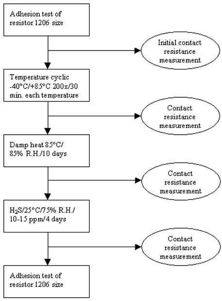
Figure 8.1 KAMILLE test plan.
8.10 Description of the tests
8.10.1 Adhesion test
The intention was to make the adhesion test with a mandrel; this test however requires a hole beneath the component in order to push the mandrel through. This is unlikely to perform on production boards (substrates). Therefore the values from a mandrel test will be stand-alone values. To be able to compare the adhesion test performed in this project to what is possible on production boards, it was decided to perform the adhesion test as a shear strength test.
Adhesion test was performed as a shear strength test, like MIL-STD 883C method 2019.2 of 1206 resistors with both Ag/Pd and Sn/Pb component finish.
Seven resistors of each terminal finish were shear tested initially and after the H2S exposure.
The test substrate layout is shown on Figure 8.2 with letters related to each test pattern described below.
 |
Figure 8.2 Test patterns on test substrate.
Test pattern A: Left side of the substrate
Mounting of 23 0-W 0603 resistors with tin lead on nickel barrier finish for 4terminal contact resistance measurement.
Measurement through 1) Substrate conductor – 2) Adhesive – 3) Component terminal – 4) Component – 5) Component terminal – 6) Adhesive – 7) Substrate conductor, where the resistance of the substrate conductor, component terminal, component, and interface between component terminal and component are assumed to be constant throughout the test programme leaving the adhesive and its interface to the substrate and to the component terminal to vary.
Test pattern B: Right side of the substrate
Mounting of 23 0-W 0603 resistors with silver palladium
finish for 4-terminal contact resistance measurement.
Measurement through 1) Substrate conductor – 2) Adhesive – 3) Component terminal
– 4) Component – 5) Component terminal – 6) Adhesive – 7) Substrate
conductor, where the resistance of the substrate conductor, component terminal, component
and interface between component terminal and component are assumed to be constant
throughout the test programme leaving the adhesive and its interface to the substrate and
to the component terminal to vary.
Test pattern C: Middle/top of the substrate
Mounting of 16 0-W 1206 resistors with silver palladium
finish and 16 0-W 1206 resistors with tin/lead on nickel
barrier finish for shear test initially and after final the environmental exposure.
The footprint could not be used for shear test of soldered components, as there was no
space for a solder meniscus on the footprint.
Test pattern D: Footprint for surface mounting of 3 electrolyte capacitors (from the Danfoss A/S case)
The electrical conductive adhesive/solder joint was visually inspected initially and after test exposure for degradation, colour change, cracks, etc.
Test pattern E: Footprint for 4 SOT319-1, Plastic quad flat package (QFP44)
Pitch: 1.0 mm.
The component was not available from the vendor. The printing on the footprint was
visually inspected for printing quality, short circuit, degradation, colour change,
cracks, etc.
Test pattern F: Footprint for 4 SOT389-1, low profile quad flat package (LQFP44)
Pitch: 0.8 mm.
The electrical conductive adhesive/solder joint was visually inspected initially and after
test exposure for short circuit, degradation, colour change, cracks, etc.
Test pattern G: Footprint for 4 SOT136-1, plastic small outline package (SO28)
Pitch: 1.27 mm.
The electrical conductive adhesive/solder joint was visually inspected initially and after
test exposure, for short circuit, degradation, colour change, cracks, etc.
Test pattern H: Middle/bottom of the substrate
Electrical conductive adhesive/solder paste was printed on and between the footprint
making a short circuit with the adhesive/solder paste.
5 of the short circuit pattern was 4-terminal contact resistance measured before and after
each environmental exposures.
After the final contact resistance measurements one of the short circuit pattern was
current/temperature tested.
Test pattern for insulation resistance/silver migration
Insulation resistance / silver migration of electrical conductive adhesives has been investigated in a previous report [27]. The result from this report stated that: No migration or indication of migration could be identified using microscope up to 100x enlargement.
This was in general the result for all adhesive variants. The no-migration result was confirmed by the insulation resistance measurements.
The no-migration results are, however, valid as long as the adhesive media encapsulates the silver particles.
Migration of the silver conductors on both the ceramics and the polyester substrate is beyond this project and has therefore not been investigated.
An investigation of silver migration of min. 10 m m electroplated silver on copper conductors is found in [28].
8.11 Current - temperature
The results after the current/temperature test are shown in table 8.2.
To have adhesive joint heated up to 105�C in equipment will not be suitable for most applications, and will reduce the reliability of the whole equipment if not cooled. Therefore, the electrical conductive adhesives must be used with low currents and cannot be recommended for power use without cooling.
In table 8.2 it is seen that highest current values are found for the ceramic substrates, this was expected due to the temperature coefficient of ceramic substrates.
8.12 Discussion
A very important parameter seems to be the component mounting pressure. A too high mounting pressure will tend the adhesive to flow-out, which may result in short circuit after the curing. On the other hand a too low mounting pressure may cause very high contact resistance of the interconnection.
Therefore, process optimising with electrical conductive adhesive may be a hard task.
The stencil printing was performed by hand as contact print with a stainless steel stencil. This may not be the most optimum process for large-scale production.
The use of snap-off printing with a polymer stencil or screen may give better printing results (recommended by Loctite). This has not been tested in this investigation, but should be considered.
Some flow-outs of the adhesives have been observed. This flow-out can be avoided by process optimising, either by reducing the stencil thickness or the printing area on the footprint. Reducing the stencil thickness will, however, result in a faster worn down of the stencil. Reducing the opens in the stencil may be a problem for the fine pitch components due to the distribution of the conductive particles in the adhesive during the printing process. With a sufficiently stirred adhesive with sufficiently small conductive particles this should not be a problem.
Regarding solder paste, it is even more important that the viscosity of the adhesives is constant over time and from lot to lot, as the self-alignment and the contraction effect are not present for the electrical conductive adhesives like it is for solder paste. The environmental humidity, which is an important parameter for solder paste, may not be as critical for the electrical conductive adhesive. This has, however, not been investigated. For the adhesive it is important that the adhesive will not create skin, especially from the printing process to the mounting process.
The visual inspection after the H2S exposure has shown a colour change for all electrical conductive adhesives with silver and for the silver palladium component terminals. The colour has become dark or black; this is what could be expected for silver in hydrogen sulphide environment. This colour change may be expected over time for silver, as hydrogene sulphide is in the atmosphere.
Contact resistance for a component to substrate interconnection may depend on the circuit. Normally low contact resistance is required, but for components with relatively high input impedance (LCD display) a high resistance may be accepted.
Comparing the contact resistance values from the short circuit pattern with the values from the component mounted pattern, there is, in general, seen a somewhat lower standard deviation for the short circuit pattern.
It was assumed that this was due to the handmounting process, however if hand-mounting has caused the relative high standard deviation, handmounting of components in electrical conductive adhesives may be a serious problem. As a result of this, prototypes or engineering models with electrical conductive adhesives may first be manufactured after optimising the mounting process.
Single measured contact resistance and samples with no failure throughout the test sequence were observed.
The high standard deviation can therefore also be assumed to be due to an inhomogeneous distribution of the conductive particles in the adhesive after the curing process or due to different oxidation degrees of the surfaces to be glued.
The mounting process is assumed as follows: When the component is pressed into the adhesive the conductive particles will be pressed down as well, and stay there due to the gravity. This may result in less conductive particles on the top of the joint where the component is attached which may result in higher contact resistance. A high conductive particle density will of course minimise this effect.
The 2 kg and above limit for the shear strength test is estimated as an acceptable shear strength value for a 1206 chip resistor. The shear strength test is, as the contact resistance possible dependent on the hand-mounting process, and it will also be a question of mounting force contra flow-out of the adhesive.
In order to avoid the effect of shear strength of the electrical conductive adhesive, the components can be glued to the substrate with a non-conductive adhesive with high shear strength force value. This may, however, add an extra process to the production flow, if a dispenser for 2 adhesives is not used simultaneously.
The initial minimum shear force value may be due to the hand-mounting process, but may indicate that process optimising is necessary for a variant with minimum shear strength value below 2 kg.
For both contact resistance and shear strength the thickness of the adhesive joint is important, and the process optimising shall be related to this. Normally, a thin joint is preferred.
The curing time is important as well, if the manufacturer gives minimum times for the curing, due to the total processing time, and insufficient curing can result, this may give at higher contact resistance and a lower shear strength values.
Initially, the contact resistance was very high for some of the variants, but after the temperature cycling the contact resistance had decreased to 'normal'.
Due to the possibility of silver migration, it may be necessary to conformal coat circuits connected with electrical conductive adhesives. The reaction between a electrical conductive adhesive and a conformal coating must be reliability tested before production.
For the current/temperature test it shall be noted that the highest current values were found on the ceramic substrates, which was expected due to the temperature coefficient of the ceramic substrate. Power circuits with components connected with electrical conductive adhesives on FR-4 are not recommended, without cooling.
8.13 Comments to each electrical conductive adhesive variant
Comments to each electrical conductive adhesive variant are given below.
The conclusion below does not compare the actual measured contact resistance values, but
only the increase of contact resistance from the initial value. This may give some
variants a bad assessment even if the contact resistance is lower as a variant which have
shown good results.
Variant no. 1, Amino CE 3511, tested on ceramic substrate with silver conductors
The adhesive has shown good results after all environmental exposures as used as a
short circuit and to connect 0603 resistors with silver palladium finish. To connect the
0603 resistor with tin lead finish the results were acceptable. However, it is seen from
the calculated mean value that for the tin lead finish the resistance has been lower and
the standard deviation higher compared to silver palladium finish.
Shear strength values were acceptable for both component finishes.
Variant no. 2, Ablebond 8175A, tested on ceramic substrate with silver conductors
and FR-4 substrate with gold over nickel conductors and tin lead conductors
For the ceramic substrate the adhesive has shown good results after all environmental
exposures as used as a short circuit and to connect 0603 resistors with silver palladium
finish. To connect the 0603 resistor with tin lead finish the results were acceptable
after temperature cycling but not after the humidity and H2S exposure. A
greater fall in contact resistance was measured after temperature cycling for both 0603
resistor types.
For the FR-4 substrate with gold over nickel plating the adhesive has shown good results
after all environmental exposure as used as a short circuit and to connect 0603 resistors
with silver palladium finish. To connect the 0603 resistor with tin lead finish the
results were unacceptable.
For the FR-4 substrate with tin lead plating the adhesive has shown acceptable results after all environmental exposure as used as a short circuit. To connect 0603 resistors with silver palladium and with tin lead finish the results were not acceptable.
Shear strength values were acceptable for both component finishes on ceramic and FR-4 substrate with gold over nickel finish. Other values were unacceptable.
Variant no. 3, Namics XH9626, tested on ceramic substrate with silver conductors and
FR-4 substrate with gold over nickel conductors and tin lead conductors
For the ceramic substrate the adhesive has shown good results after all environmental
exposures as used as a short circuit and to connect 0603 resistors with silver palladium
finish. To connect the 0603 resistor with tin lead finish the results were
unacceptable.For the FR-4 substrate with gold over nickel plating the adhesive has shown
good results after all environmental exposure as used as a short circuit and to connect
0603 resistors with silver palladium finish. To connect the 0603 resistor with tin lead
finish the results were unacceptable.
For the FR-4 substrate with tin lead plating the adhesive has shown acceptable results
after all environmental exposures as used as a short circuit. To connect 0603 resistors
with silver palladium and with tin lead finish the results were unacceptable.
Shear strength values were acceptable for both component finishes on all substrate types.
Variant no. 4, Loctite 3880, tested on polyester substrate with silver conductors
and FR-4 substrate with gold over nickel conductors and tin lead conductors.
For the polyester substrate the adhesive has shown good results after all
environmental exposures as used as a short circuit and to connect 0603 resistors with
silver palladium finish. To connect the 0603 resistor with tin lead finish the results
were unacceptable. For the FR-4 substrate with gold over nickel plating the adhesive has
shown good results after all environmental exposures as used as a short circuit and to
connect 0603 resistors with silver palladium finish. To connect the 0603 resistor with tin
lead finish the results were unacceptable.
For the FR-4 substrate with tin lead plating the adhesive has shown unacceptable results
after all environmental exposure as used as a short circuit and to connect 0603 resistors
with silver palladium and with tin lead finish.
Shear strength values were acceptable for both component finishes on FR-4 substrate with
gold over nickel finish and with tin lead finish. Shear strength values on polyester
substrate were unacceptable
Variant no. 5, Loctite 3882, tested on polyester substrate with silver conductors
The adhesive has shown good results after all environmental exposures to connect 0603
resistors with silver palladium finish. To connect the 0603 resistor with tin lead finish
the results were unacceptable.
When used as a short circuit the results were only acceptable after temperature cycling.
Shear strength values were acceptable for Ag/Pd component finish on polyester substrate
but for Sn/Pb components finish the values were unacceptable.
Variant no. 6, Epo-Tek H20F, tested on polyester substrate with silver conductors
The adhesive has shown good results after all environmental exposures as used as a
short circuit and to connect 0603 resistors with silver palladium finish. To connect the
0603 resistor with tin lead finish the results were acceptable, H2S may
increase the contact resistance when components with tin lead finish are used.
Shear strength values were unacceptable for both component finishes on polyester
substrate.
Variant no. 7, Multicore M-4030-SR, tested on FR-4 substrate with gold over nickel
conductors and tin lead conductors
For the FR-4 substrate with gold over nickel plating the adhesive has shown good
results after all environmental exposures as used as a short circuit and to connect 0603
resistors with silver palladium finish. To connect the 0603 resistor with tin lead finish
the results were acceptable with the same resistance values as for the components with
silver palladium finish.
For the FR-4 substrate with tin lead plating the adhesive has shown acceptable results
after all environmental exposures as used as a short circuit tin lead it and to connect
0603 resistors with silver palladium. To connect components with tin lead finish the
results were unacceptable compared with the initial value. However, the contact resistance
values were a factor 3 higher than the solder reference initially and a factor 6 higher
than the solder reference after the exposures, which may be accepted for some
applications.
Shear strength values were acceptable for both component finishes on FR-4 substrate with
gold over nickel finish and with tin lead finish.
Variant no. 8, Acheson Electrodag SMD10, tested on FR-4 substrate with gold over
nickel conductors and tin lead conductors
For the FR-4 substrate with gold plating the adhesive has shown good results after all
environmental exposures as used as a short circuit and acceptable results to connect 0603
resistors with silver palladium finish. To connect 0603 resistor with tin lead finish the
results were unacceptable.
For the FR-4 substrate with tin lead plating the adhesive has shown acceptable results
after all environmental exposures as used as a short circuit. Connecting 0603 resistors
with silver palladium has not been tested due to an assembly failure. To connect
components with tin lead finish the results were unacceptable.
Shear strength values were acceptable for both component finish on FR-4 substrate with
gold over nickel finish and for Sn/Pb component finish on FR-4 substrate with tin lead
finish. Other values were unacceptable.
Variant no. 9, Wacker Semicosil 970EC, tested on FR-4 substrate with gold over
nickel conductors and tin lead conductors
For the FR-4 substrate with gold plating the adhesive has shown unacceptable results
after all environmental exposures as used as a short circuit to connect 0603 resistors
with silver palladium finish and to connect 0603 resistor with tin lead finish.
For the FR-4 substrate with tin lead plating the adhesive has shown unacceptable results
after all environmental exposures as used as a short circuit, connecting 0603 resistors
with silver palladium, and to connect components with tin lead finish.
Shear strength values were unacceptable for both component finishees on FR-4 substrate
with gold over nickel finish and with tin lead finish.
Variant no. 10, Tecknit 72-00236, tested on FR-4 substrate with gold over nickel
conductors and tin lead conductors
For the FR-4 substrate with gold over nickel plating the adhesive has shown
unacceptable results after all environmental exposures as used as a short circuit, to
connect 0603 resistors with silver palladium finish and to connect 0603 resistor with tin
lead finish.
For the FR-4 substrate with tin lead plating the adhesive has shown unacceptable results
after all environmental exposures as used as a short circuit, connecting 0603 resistors
with silver palladium, and to connect components with tin lead finish.
Shear strength values were unacceptable for both component finishes on FR-4 substrate with
gold over nickel finish and with tin lead finish.
Variant no.11, Tecknit 72-00151, tested on polyester substrate with silver conductor
In general, the adhesive has shown unacceptable results after all environmental
exposures as used as a short circuit and to connect 0603 resistors with silver palladium
and tin lead finish. Process optimisation may prove the results for connecting components
with silver palladium finish, as good results were found for 8 out of 23 measurements.
Shear strength values were unacceptable for both component finishes on polyester
substrate.
Variant no. 12, Creative 106-22, tested on FR-4 substrate with gold over nickel
conductors and tin lead conductors
For the FR-4 substrate with gold plating the adhesive has shown good results after all
environmental exposures as used as a short circuit and to connect 0603 resistors with
silver palladium finish. The measured contact resistance values were however relatively
high, possibly due to the fact that the conductive material is carbon. To connect 0603
resistor with tin lead finish the results were unacceptable.
For the FR-4 substrate with tin lead plating the adhesive has shown unacceptable results
after all environmental exposures as used as a short circuit, connecting 0603 resistors
with silver palladium finish and with tin lead finish.
Shear strength values were acceptable for both component finishes on ceramic and FR-4
substrate with gold over nickel finish and with tin lead finish.
Variant no. 13, Tecknit 107-25, tested on polyester substrate with silver conductors
The adhesive has shown acceptable results after all environmental exposure as used as
a short circuit and to connect 0603 resistors with silver palladium finish. To connect the
0603 resistor with tin lead finish the results were unacceptable. H2S may
increase the contact resistance when components with tin lead finish are used. The
resistance value for the adhesive used as a short circuit was high compared with the other
variants used on polyester substrate.
Shear strength values were unacceptable for both component finishes on polyester
substrate.
Variant no. 14, Multicore 96SCMX39AGS88.5 Sn/Ag/Cu lead-free solder, tested on
ceramic substrate with silver conductors and FR-4 substrate with gold over nickel
conductors and tin lead conductors
All results were good.
[Front page] [Contents] [Previous] [Next] [Top] |