Guidelines on remediation of contaminated sites
4. Site investigations
4.1 Introduction
The scope of the investigation of contamination, and thus the collection of data, depends entirely on the result of the initial survey as well as the requirements for the data which are to be used in connection with the subsequent risk assessment. Part of the information from the Guidelines on sampling and analysis /3/ have been included in this chapter. This chapter includes the following main sections:
| Sampling soil and water | |
| Sampling air | |
| Methods of analysis | |
| Collection of data on buildings | |
| Geology, hydrogeology, and hydrology |
4.2 Sampling soil and water
Soil and water sampling is carried out in the investigation phase, usually from borings and monitor wells. The objective of sampling is to describe the contamination, the soil, and the groundwater to such an extent that risk analyses may be carried out, and so that there is an adequate foundation for planning and executing necessary remediation.
4.2.1 Location of soil borings
Soil borings are usually located as follows:
| in areas where contamination is expected (hot spots) on the basis of knowledge of the location of previous and existing production plants, and on the basis of other land use. | |
| near the boundaries of already known contaminated areas for the purpose of determining the extent of contamination. | |
| in areas which have, or which are suspected to have, a contamination-sensitive land use. Such areas are covered with a relatively high intensity of borings as described below. | |
| at the rest of the site, since it is not always possible to localise all hot spots during the initial survey, and as spills are often spread over large parts of a site. |
In order to reveal unknown contamination and to achieve the best statistical coverage of the site, it may be beneficial to locate borings according to specific rules. In such cases, sample fields/grids/nets can be defined. Table 4.1 describes the number of sample points which are necessary to localise unknown hot spots.
Table 4.1
Number of sample points which are necessary to locate a hot spot of given size, with
given certainty. in a 400 m2 area.
Diameter of hot spot (m) |
% contam. |
Probability |
|||
|
site % |
50%* |
90%* |
95%* |
99%* |
10 |
20 |
2 |
5 |
6 |
7 |
7 |
10 |
5 |
10 |
12 |
15 |
5 |
5 |
10 |
20 |
24 |
29 |
3 |
2 |
28 |
54 |
65 |
81 |
2 |
0.8 |
62 |
122 |
147 |
183 |
1 |
0.2 |
249 |
488 |
589 |
731 |
* Probability of localising a hot spot
For example, the table shows that if 24 sample points (borings) are placed on a 400 m2 site, there is a 95% probability of finding a contamination with a diameter of 5 m.
It is therefore financially unrealistic to localise unknown, smaller hot spots with high probability. Normally, investigations will be based on known sources of contamination and how contamination has dispersed from these. When using only a few borings, it is not possible to assume that all small hot spots have been localised, nor that the contamination has been fully delineated. It is important to stress that each boring only represents a point measurement. Therefore, the results from such point measurements should be interpreted with care during the assessment of a contamination.
The location and number of borings is described in more detail in the Guidelines on sampling and analysis of soil /3/, where there are examples of sampling strategies, and suggested sample densities if the source of contamination has not been localised, or if there are special objectives. As an absolute minimum, representative samples should be taken which correspond to a rough screening in Table 4.1.
4.2.2 Execution of borings/excavations
The objective of executing borings is to obtain representative samples to determine geological and contamination conditions horizontally and at depth. Appendix 4.1 contains more detailed guidelines on executing borings.
When carrying out soil sampling very close to the surface, borings may be replaced by excavations. Excavations are usually carried out with a trench digger. Only in rare circumstances will digging by hand be advantageous. Excavating by machine provides a good overview of the soil layers, and how the contamination varies along the face of the excavation. Excavations are particularly advantageous in cases where the contamination is distributed unevenly, for example landfills, or if an investigation of other geological conditions is desired. It is important to note that excavations are only advantageous if, prior to excavating, permission is obtained to refill the trench with the excavated soil, even if it is contaminated.
Localisation borings are shallow investigative borings of up to 3-4 m in depth. Localisation borings are made in order to describe and delineate a contamination in the upper soil layers and/or groundwater aquifers close to the surface.
Often, very shallow borings of up to 1 m are made for contamination such as metals close to the surface. These borings can usually be back filled with excavated material. If a boring is deeper than a maximum of 3-4 m, casing should be used to avoid possible cross contamination. The boring method usually used is dry rotation boring. Methods of boring and screen installation are described in detail in Appendix 4.1.
Investigation borings are borings of more than about 4-5 m where, in addition to describing and delineating a contamination in the upper, and possibly deeper soil layers, the objective is also to obtain information on deeper groundwater. Borings with this depth should always be carried out using casing in order to ensure representative soil samples and in order to prevent cross contamination when boring through several water-bearing strata. The method of boring most commonly used is dry rotation soil boring with casing. Methods of boring and screen installation are described in detail in Appendix 4.1.
Wells are installed to investigate deeper aquifers, to monitor groundwater or to remediate groundwater by pumping. Different methods of boring are described in Appendix 4.1. In many cases, wells are screened in upper aquifers.
4.2.3 Soil sampling
During boring, a set of two soil samples is usually collected at each depth. One sample is used for characterisation, including field measurements, cf. Table 4.5, and for geological descriptions. The second sample is used for chemical analyses. Sample sets are usually collected every 0.5 m. As a minimum, however, one set is collected per soil layer.
Methods of sampling, packing, handling, and storage should be adapted to the type of contamination. It is vital that guidelines are followed, especially for volatile contamination, as investigations will otherwise lose their value. Guidelines on soil sampling are described in more detail in Appendix 4.2 and in the Guidelines on sampling and analysis of soil /3/.
4.2.4 Water sampling
The objective of sampling is to obtain a water sample from the well which is representative of the aquifer with regard to the parameters to be investigated.
Water samples are usually collected from screens in wells. In screened localisation borings, it is normal to install screens only in the upper saturated zone. Placement of screens in investigation borings depends on the hydrogeological conditions and the specific objectives of the borings, cf. Appendix 4.1.
Sampling comprises three phases:
| Purging | |
| Sampling | |
| Sample storage |
There is a distinction between well development and purging. Immediately after a well is completed, well development should be carried out by pumping in order to achieve the best possible well efficiency. Well development can be conducted as part of stepwise pump test, cf. Section 4.2.5.
The groundwater in screened investigation borings is in contact with the air. This means that the temperature, the oxygen content and the carbon dioxide content of the groundwater in the well and its immediate vicinity can be significantly different from conditions within the aquifer. These differences can also mean that the content of contaminants is not the same in the aquifer and the well, due to chemical and biological activity. Furthermore, there is a risk that volatile compounds will have evaporated from the water in the well.
In order to ensure collection of a sample which represents the groundwater aquifer as well as possible, purging should be carried out prior to sampling. Different types of pumps are used for purging and water sampling, depending on the nature of the boring and the hydraulic conditions. The various types of pumps and the approach to purging are described in more detail in Appendix 4.3.
The objective of sampling is to obtain a water sample from the aquifer via the well. During this phase, there are three factors in particular which are significant:
| The equipment should not contaminate the sample. | |
| The equipment should not be made of materials which ad/absorb substances. | |
| The method should not bias the contaminant content of the sample. |
Water sampling is described in more detail in Appendix 4.3. Appendix 4.10 provides examples of forms which can be used for water sampling. Some parameters should be measured on site (O2, CO2, Ek (redox potential) and pH), as these may change if the sample is transported.
The packing which is used to store the sample during transport to the laboratory should ensure that the samples change as little as possible. The sample container should be cleaned by the laboratory before delivery to the site. Water samples which are to be analysed for organic parameters should be stored in glass flasks with tight lids. Samples which are to be analysed for inorganic parameters, e.g. heavy metals, are often stored in plastic bottles. For certain parameters, the laboratory will provide sample containers which are specially cleaned, or which contain a preservative.
Water samples should be stored in the dark and kept cool (40C). The time from sampling to analysis should be kept to a minimum. As far as possible, samples should be delivered to the laboratory on the same day they are collected. If this is not possible, it should be noted on the analysis form.
4.2.5 Execution of pump tests
Pump tests are carried out to determine the physical and geometric properties of the groundwater aquifer. Pump tests provide information on the water level as a function of time, yield, and distance.
A step-test is carried out to determine the characteristics of the well. Well loss arising from the screen and the total well efficiency is determined. A step test is therefore primarily performed to demonstrate ‘how good the well is’, i.e. how much the well can produce in relation to the potential yield of the aquifer.
Immediately following the well completion, development of the well should be executed, possibly as a beginning of a step-test. Thus, in addition to developing the well, information is also obtained on how good the well is and possibly on the hydraulic parameters of the aquifer.
Pumping is usually carried out as a minimum in a three-step test with variable yields, according to the regulations in the Statutory Order on Execution of Groundwater Wells /6/. Regular yield measurements should be taken at all steps. Head measurements should be more frequent at the start than at the end of the test, for example as described in Appendix 4.9. After the final step, head recovery in the well is measured with the same time intervals. From this data, well efficiency and well loss can be calculated.
Pump tests at constant capacity are carried out in order to determine the hydraulic parameters of the groundwater and the horizontal limits of the aquifer. In principle, an investigation of a groundwater aquifer with a pump test is carried out by pumping at a constant capacity from an individual well while observing the drawdown in selected observation wells (well test using drawdown data). After pumping is stopped, recovery in the observation wells is measured to obtain control measurements (well test using recovery data).
The drawdown/recovery which is observed is treated as a function of time and distance, and is interpreted to determine the hydraulic properties of the aquifer; transmissivity, storativity/specific yield, and leakage. Furthermore, information may be obtained on the aquifer’s boundary conditions, recharging boundaries (e.g. watercourse) or discharging boundaries (e.g. clay aquitard). Information can also be obtained on the anisotropy of the aquifer.
Once interpretation is completed, it is in principle possible to calculate future drawdown for any given yield, possibly as an aid in designing groundwater remediation using the pump-and-treat technique. A more detailed description of pump tests is included in Appendix 4.9.
4.3 Air sampling
4.3.1 Measurements of organic and inorganic gases in soil gas
In the unsaturated zone, contaminants are distributed in three phases: absorbed on the soil, dissolved in the soil water, and as gas dissolved in the soil gas (with heavy contamination, there can also be contamination components in a separate phase). The distribution between the three phases depends on the physical/chemical properties of the contaminants.
A greater proportion of soil contamination will be gaseous for volatile compounds. As a result, it can often be advantageous to carry out soil gas measurements when investigating the contamination, taking into account that the soil must have a certain conductivity.
Soil gas measurements are typically used for highly volatile hydrocarbon contaminants, such as benzene, toluene, and xylenes, or for chlorinated solvents. However, soil gas measurements can also be used for other contaminant components, such as naphthalene and hydrocyanides.
Soil gas measurements are particularly useful for:
| Risk assessment of very sensitive area land use, including contamination of indoor air. | |
| Preliminary contamination investigations where contamination with volatile compounds is suspected. | |
| Mapping the extent of soil contamination or groundwater contamination near the surface. | |
| Localising point sources of identified soil or groundwater contamination, for example at landfills. |
Soil gas measurements are carried out by ramming a probe down to a given depth in the unsaturated zone. Soil gas investigations can also be carried out from a vehicle specially equipped with sampling and analysis equipment. The typical sampling depth is 1-5 m, depending on the objectives, geology, and expected contamination. Soil gas is pumped up from the probe and is collected for subsequent analysis in, for example, tedlar bags or on adsorption tubes. The method of collection depends on the method of analysis chosen. When assessing indoor air risks, soil gas measurements can also be carried out in the capillary-breaking layer under the floor of a building. Methods of measurement are described in more detail in Appendix 4.4.
The subsequent analyses can either be conducted as field measurements using PID instruments (photo-ionisation detectors), portable gas chromatographs, etc. or they may be conducted in the laboratory. The advantage of field measurements is that results are available immediately after samples are collected and thus ongoing adjustments can be made to the investigation. However, laboratory analyses have the advantages of less uncertainty and lower detection limits.
Selection of the method of analysis depends on the application of the soil gas measurements. For delineation of a known contamination, where rapid results may be important, it is most appropriate to carry out field measurements, while for preliminary contamination investigations or for assessment of risks to the indoor air, analyses in the laboratory may be more appropriate.
4.3.2 Landfill gas
The primary objective of gas investigations at landfills and tips where biodegradable waste has been deposited is to obtain an assessment of whether the methane gas which percolates up can lead to a risk of explosions in buildings on the site or in the immediate vicinity.
Appendix 4.5 provides brief information on landfill gas. Investigations prior to a risk assessment includes:
| Data collection of the conditions at the landfill, including local geologic and groundwater conditions. | |
| Determination of the gas-generating areas, including the pressure conditions in the area. | |
| Data collection of building conditions, including underground cables and pipes. |
To start with, accessible (historical) knowledge of the parameters which have an influence on gas generation and gas transmission out of the site is acquired.
Table 4.2 provides a checklist which can be used in collecting this information.
Table 4.2
Checklist of conditions at a landfill/deposit
|
In order to identify the areas generating gas, including identifying the strength of the
source, soil gas measurements must be taken at the site. Appendix 4.6 describes guidelines
for conducting soil gas measurements of landfill gas.
Seasonal variations, meteorological conditions, etc. affect results significantly. It is therefore advisable to carry out soil gas measurements of landfill gas three times over a year before making final decisions. Endeavours should be made to carry out measurements under situations where the surface is saturated with water, or covered with snow, when there is a change from high to low pressure, and at high ground temperatures.
As gas may be transmitted horizontally in porous soils, soil gas measurements should cover both the landfill site and any nearby critical areas. The potential critical distance depends on the local geology. Illustrative critical distances are provided in Table 4.3.
Table 4.3
Potential critical distances from landfills, cf. Figure 4.1
Moraine clay Fine sand Coarse sand |
10 m 25 m 250 m |
It is advantageous to locate soil gas measuring points in a grid (e.g. 50 x 50 m). A
diagram of suggested measuring points for an investigation is shown in Figure 4.1. Section
5.3.3, reviews results analysis, including assessment of the actual critical distance.
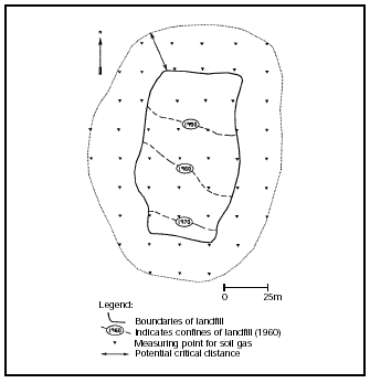
Figure 4.1
Illustration of measuring points for investigations of landfill gas
Figure 4.1 shows the boundaries of an old quarry which has now been landfilled. The quarry was landfilled from north to south from about 1940 to 1972. With the aid of aerial photographs, the progress of the landfilling can be identified at various points in time. The local geology comprises primarily fine sand. Table 4.3 below shows the potential risk of critical gas dispersion to a distance of 25 m from the edge of the landfill.
In order to investigate whether landfill gas is still being generated at the site, soil gas measurements are taken at a large number of soil gas measuring points. The measuring points are located in a network of about 25m x 25 m.
In order to be able to assess the risk of gas penetrating a building located on or near to the landfill, information should be collected on how the building is constructed. Furthermore, information should be obtained on underground cables and pipes, as well as possible other underground installations where there is a risk of spreading the gas. Table 4.4 provides a checklist for this purpose.
Table 4.4
Checklist of construction conditions of a building.
|
Information on the construction of buildings can be collected after the gas-generating
area has been identified and the actual critical distance for surrounding buildings has
been determined, cf. Figure 5.8 in Section 5.3.3.
4.3.3 Indoor air
In special cases, it may be necessary to conduct indoor air investigations in existing buildings in connection with health assessments of the indoor air. Methods and procedures for measuring air quality are described in guidelines from the National Housing and Building Agency on measuring substances in indoor air arising from soil contamination /7/. As a minimum, measurements should be made in three areas:
| The place in the building where the greatest concentration of contamination from the soil is expected. | |
| The place in the building where there is least risk of finding contamination from the soil. This place should be in frequent use by the residents. | |
| Some typical concentrations from outdoor air. |
The measuring sites and the number of series of measurements are set on the basis of the above. Furthermore, there are a number of factors which can have a crucial effect on the results of the measurements, e.g. barometric pressure, wind velocity, air pressure in the building, indoor activities and building materials. The significance of individual factors is described in the guideline from the National Housing and Building Agency /7/, which includes recommendations on what should be done.
4.4 Methods of analysis
The objective of analysing soil and water samples is to identify the degree of contamination in the area being investigated.
There are various methods of analysing soil and water samples. The methods of analysis vary in price, speed of analysis, the type of substance to be analysed, detection limits, accuracy in quantifying the content, and precision.
Many screenings or on-site methods are less accurate than other analyses, but they provide results for more substances in the same analysis. Some on-site methods do not allow direct quantification of the content of individual contaminants, but provide more qualitative indications of whether there is a high or low content of specific types of substances.
When investigating unknown contamination, there is a need to analyse for a broad spectrum of substances. Here, it can be an advantage to utilise these less accurate, but broader, methods of analysis in order to achieve a wider description of the contamination. The number of analyses is more significant in localising or delineating a contamination with certainty rather than the accuracy of an individual analysis.
4.4.1 Field methods
The various types of field methods are listed in Table 4.5. The methods range from non-specific to substance-specific.
Table 4.5
Field methods and analysis parameters /3/.
Field method |
Analysis parameters |
Non-specific methods |
|
Visual assessment |
Oil, tar, slag, cyanides |
FID |
Chlorinated solvents, petrol, phenols, oil, (tar) |
PID |
Chlorinated solvents, petrol, phenols, oil, (tar) |
Contamination-specific methods |
|
Immunoassay |
Oil, petrol, PAHs, polychlorinated phenols, TNT |
Infrared spectroscopy |
Oil, petrol, chlorinated solvents |
Test tube |
Petrol, water miscible solvents, chlorinated solvents, cyanides |
Colour reaction |
Petrol, oil, polychlorinated phenols, (metals) |
Electrochemical potential* |
Oil |
Fluorescent measurements (UV)* |
Oil, tar |
Optic fibre techniques* |
Oil, petrol, chlorinated solvents |
Substance-specific methods |
|
GC/PID/FID/ECD, headspace over soil, extraction of soil |
Petrol, oil, chlorinated solvents, water miscible solvents |
EDXRF |
Heavy metals |
Thin layer chromatography* |
Oil, tar, pesticides, polychlorinated phenols |
*Methods under development
The most commonly used non-specific method is measurement of volatile organic substances using a photo-ionisation detector (PID) or a flame-ionisation detector (FID). Measurement with a PID is described in more detail in Guidelines on sampling and analysis of soil /3/. The FID functions on the same principle as the PID, but it has a different type of detector which covers a larger area than the PID.
This method measures the air immediately above the soil sample. Therefore, only volatile substances in the gaseous phase are measured. Portable gas chromatographs are available with different detectors. The most common is the photo-ionisation detector. Besides this, there is the flame-ionisation detector and the electron capture detector (ECD). Gas chromatographs are substance specific, i.e. individual substances can be detected using this method.
X-ray fluorescent measurements for heavy metals are either carried out using portable field equipment directly on the soil, or in the laboratory, after soil samples have been collected. The method is metal specific. There are different sensitivities for individual heavy metals, and therefore different detection limits. The equipment contains a radio-active source which decays over time. This means that the sensitivity of the instrument declines over time, and it should be maintained according to the manufacturer’s instructions. Since the method is very sensitive to the soil type, field measurements should usually be checked with laboratory analyses.
There are various types of field methods where the type of contamination can be determined using solvents which produce a colour reaction which depends on the amount of contamination present. The different methods and the types of contamination which can be detected are described in more detail in the Guidelines on sampling and analysis of soil. /3/.
4.4.2 Laboratory analyses
As a rule, approved laboratory analyses should be carried out during contamination investigations. The analyses should identify potential contamination, quantify the substances, have a detection limit that corresponds to acceptance criteria (the detection limit should be no higher than 1/10 of the acceptance criteria) and have an acceptable accuracy (typically a standard deviation of 10-20 %).
Laboratory analyses can either be carried out as screening analyses, or as substance-specific analyses. Screening analyses are normally utilised when the contamination parameters are not known, and where it is important to investigate for a number of substances. When contamination is found, a number of samples can be examined using specific analyses. The different methods of analysis are listed in the table included in Appendix 4.7. For further details of laboratory analyses, see the Guidelines on sampling and analysis of soil /3/.
4.5 Collection of data regarding buildings
When investigating the indoor air, or before implementing remedial measures for volatile substances and landfill gases, it is necessary to examine existing buildings, cf. guidelines from the National Building and Housing Agency /7/.
Background information on buildings can be obtained from the local authority, from the Land Registry Office, from previous and current owners, from investigations, etc. Information should include:
| The age of the building | |
| The construction of the building | |
| Thickness of materials and floor construction in contact with the soil | |
| Presence of reinforcement and concrete quality | |
| Height of rooms | |
| Renovation works carried out | |
| Current and previous use of the building, production etc. | |
| Cables and pipes. |
In a subsequent investigation, the extent of agreement between the background information obtained and the actual conditions is examined. Furthermore, the following is examined:
| Whether there are visible cracks in the floor /16/. | |
| The quality of the building construction immediately above the soil, e.g. whether pipe lead-ins are air tight /16/. | |
| Whether the building itself, its land use, fittings, activities in the building, or any storage can lead to contamination of the same type as that which may be under the building. | |
| The surroundings of the building for sources of air pollution which may cause the same type of contamination as that which may be under the building. | |
| Whether there are signs of dampness (or similar) from the ground. | |
| Smells and odours in the building | |
| Ventilation. |
The above information is used in the overall assessment of the condition of the building, and in assessing the construction measures necessary to secure the quality of indoor air, see the Guideline on Surveying Air in Building Constructions /16/.
4.6 Geology, hydrogeology, and hydrology
During an investigation of contamination, geological and hydrogeological conditions should be elucidated. The relevant soil strata should be described geologically. In addition to utilising basic data, this description is prepared primarily on the basis of geological characterisation of soil samples from the investigation borings. These may be supplemented with geotechnical tests and geophysical measurements. The scope of the geological description is detailed in Appendix 4.8. For further information regarding the geological description, refer to DGF’s Guidelines on Sample Description /8/.
The hydrogeological description details relevant groundwater conditions. The groundwater aquifer is assessed on the basis of the geological description and groundwater observations in the wells. Furthermore, these can be supplemented with pump tests, cf. Section 4.2.5, and possibly groundwater models. Water flow in the individual groundwater aquifer can now be determined in the form of the potentiometric surface, flow direction, gradient, hydraulic parameters, and leakage.
Surface water recipients in the area should often be mapped during a contamination investigation. When the recipient is located close to the contaminated site, investigations should be made as to whether contamination has taken place. Contamination can occur through groundwater flow or surface run-off. In most investigations, contamination from groundwater is the most critical.
On the basis of the geological model and water-level measurements from the groundwater and from the recipient, assessments can be made as to whether the contamination can reach the recipient. If this is the case, the concentration contribution of the contaminants is calculated on the basis of analyses of groundwater samples collected close to the recipient, taking into consideration mechanisms such as mixing, degradation, and sorption.